The input can be a Cloud, an Outer Boundary, or both. You can also define Inner Boundaries.
You can select an Init Surface for better result.
- Open the PowerFit1.CATPart from the Sample directory.
This model consists of a mesh (Polygon) and curves. - Read Information about Power Fit.
- Information displayed in the graphic area corresponds to the current tab.
-
Click PowerFit
 .
The dialog box is displayed:
.
The dialog box is displayed:
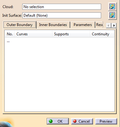
This command is modal: The values used are re-displayed the next time you open this dialog box. -
Select the Cloud.
It can be either a cloud of points, or a mesh, or a portion of these.
You can process only one cloud or one mesh at a time.
The name of the cloud is displayed in the dialog box.
Once selected, the cloud is sent to the NoShow space. -
If you are working in Datum mode:
Click") that has become active once you have selected a cloud of points or a mesh,
that has become active once you have selected a cloud of points or a mesh,
and activate the portion of Cloud you want to process. -
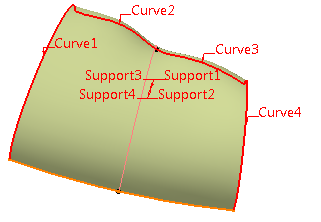
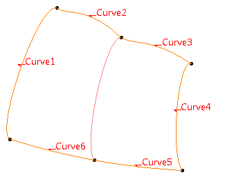
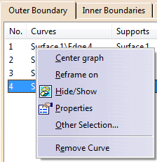
Select the curves that will form the Outer Boundary.
The Outer Boundary tab is updated with the names of the curves.
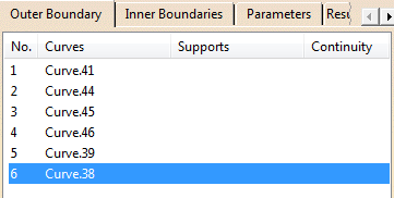
The curves are hightlighted in the graphic area.
-
If required, add a support surface to a curve.
In that case, the curve must lie completely on the surface you select. -
If required, place the cursor in Init Surface, and select one to improve the result surface,
especially in rounded areas.
The Init Surface must be larger than the domain to process.
If you do not select an Init Surface, Power Fit computes one in the direction of the largest curve. -
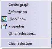
Click
 to hide or show the Cloud or the Init Surface.
 -
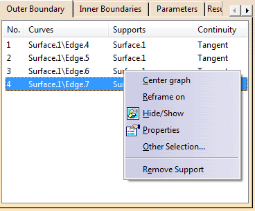
If required, right-click one selected element and use its contextual menu to remove it.
For Cloud or Init Surface:
For a curve:
-
Go to the Inner Boundaries tab.
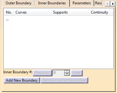
- Click Add New Boundary and select
the curves that will form
this boundary.
You can remove a curve, add or remove a support, or change the continuity as explained for Outer Boundary. - Inner and outer boundaries cannot intersect, be merged or be the same.
- Repeat to add another
boundary.
Inner Boundary # shows the number of created inner boundaries.
Use Previous and Next to navigate through them.
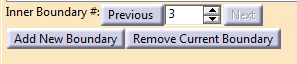
- Go to the required boundary, and click Remove Current Boundary to remove it.
- Click Add New Boundary and select
the curves that will form
this boundary.
-
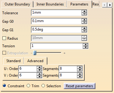
Choose the way the input curves are taken into account:
- As Constraint: The computed surface will go through them.
- As Trim: The surface is computed, then the curves are projected onto it to trim it.
- As Selection: The computation is based on the points located inside the curves.
-
Enter a Tolerance, i.e. the mean deviation between the surface created and the could of points or mesh.
The actual deviation may be higher at some places.
By default, the Tolerance is set to 1mm. -
Key-in Gap G0, i.e. the distance between the surface and the boundary curves.
Since there is more noise on points than on curves, the Tolerance may be higher than Gap G0.
By default, GAP G0 is set to 0.1mm. -
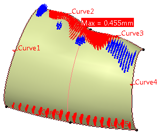
Key-in GAP G1, i.e. the tangency tolerance between two contiguous surfaces (in blue below).
By default, Gap G1 is set to 0.5deg. -
Key-in the Tension.
Possible values are between 0 and 4. Use a higher value for a tenser surface.
Since the shape is constrained by the points, the effect of this parameter is limited. -
If required, select the Radius check box.
This radius is editable.
When the cloud of points is noisy, it is difficult to have the surface going through
all the points and the curves (risk of undulations).
The points inside a circular pipe centered on the curve are deleted,
and you may want to set the radius of that pipe.
When you select this check box, a blue sphere is displayed on the extremity of the first curve,
representing this radius (if you have selected at least one curve and a cloud of points or a mesh).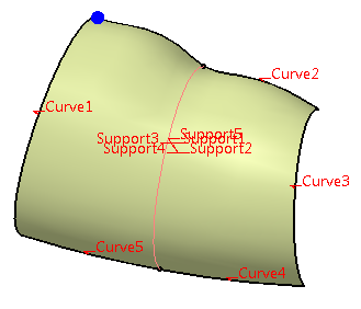

If two curves are not distant enough, all the points between them may be deleted,
making the computation of the surface impossible.
-
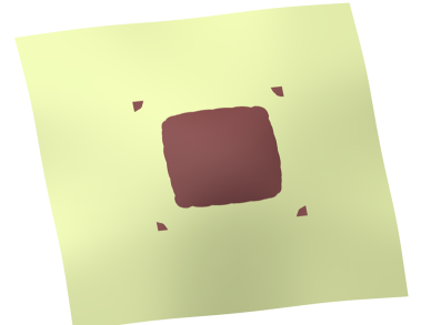
Select the Extrapolation check box, and define its value with the slider.
The Extrapolation check box is available if:- You have only selected a Cloud (no Outer Boundary).
- You have selected a Cloud and an Outer Boundary, and the option Selection.
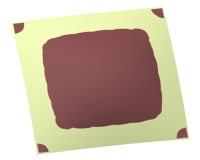
When Extrapolation is not selected:
When Extrapolation is selected:
By default, Extrapolation is not selected.
-
In the Standard tab, key-in the Order and Segments for the resulting surface.
- These parameters apply globally to the surface computed.
- They are maximum values.
-
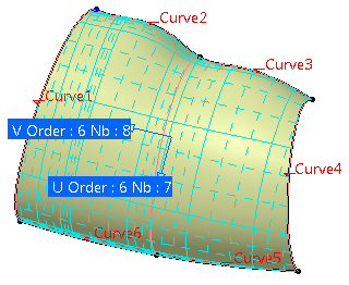
If required, go to the Advanced tab.
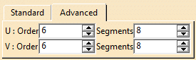
Impose an order and a number of segments in both U and V directions.You can: - Key-in the number of segments in each direction.
- Key-in the order of segments in each direction.
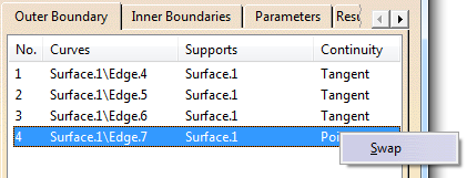
- Swap the values in U and V.
-
Go to the Results/Display tab to check the deviations.

-
Once you are satisfied, click OK to validate and exit the dialog box.
A Power Fit feature is created. It is editable by double-click.
It is automatically updated if you replace the Cloud by another one, edit parameters, or add/remove/modify curves.