|
-
Click Solid Blend Corner
 in the
Dress-Up Features toolbar. in the
Dress-Up Features toolbar.
| The Blend Corner Definition dialog box appears. |
-
Select two or more faces.
 |
- All the selected faces must belong to the same global
support.
- The Global support box is automatically
filled by the solid containing the selected faces.
|
-
Click Preview.
-
From the Sections list, you can:
- Click Remove section to remove a selected section.
- Click Replace section to replace a selected section with another section.
- Click Swap direction of section to reverse the orientation of the selected section.
- Change the setback values for individual faces using the
Setback box. You can click Apply to all
if you want to apply the same setback value to all faces.
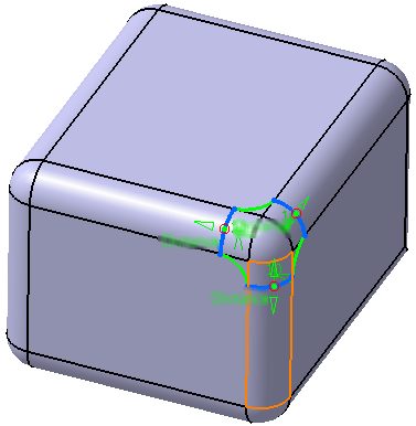
You can also use the manipulators in the 3D to change the
setback values.
|
-
Move the manipulator arrows to edit the point on the
solid.
-
Optional: Click Reverse sew result to inverse the
orientation of the blend corner.
-
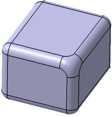
Click OK to create the blend corner.
The element (identified as
Blend Corner.xxx) is added to the specification
tree.
|