|
Sewing is a Boolean
operation combining a surface with a body. This capability adds or removes
material by modifying the surface of the solid. You can sew all types of
surfaces onto bodies. Depending on your geometry, two kinds of sewing
operations can be performed:
- If the surface has been designed so that its boundary entirely lays
on the solid, you can sew it using the surface boundary projection onto
the solid. In this case you can use the
Simplify geometry check box.
Sewing features (in boundary projection mode) is more productive (CPU
cost) and more stable (geometric tangency condition) than creating a solid
using the Close Surface command (when
possible) because no surface/surface intersections are computed.
-
If the surface crosses the solid, you can make the
application compute the intersection of the surface with the solid prior
to sewing the surface. In this case, you need to use the
Intersect body
option.
This task shows you both methods. |
 |
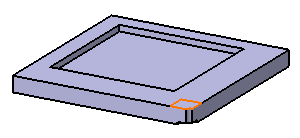
Open the
SewSurface.CATPart document. |
 |
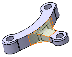
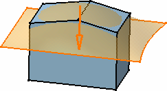
-
The surface boundary is on the solid. Select Join.1
as the surface you wish to sew onto the body.
-
Click Sew Surface
 . .
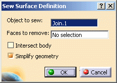
The Sew Surface Definition dialog box is displayed:
Keep the Simplify geometry option active.
Using this option, if in the resulting solid there are connected faces
defined on the same geometric support (faces separated by smooth edges),
these faces will be merged into one single face.
Arrows appear indicating the side where material will be added or kept.
Note that clicking an arrow reverses the given direction. The arrows must
point towards the solid.
-
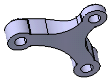
Click OK.
The surface is sewn onto the body. You may notice that the bottom of the
solid is made of one single face. The specification tree indicates you
performed the operation.
-
To see the simplification, just hide Join.1.
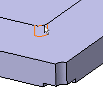
Some operations you perform after sewing using
Simplify geometry may make the simplified geometrical result
disappear. As shown in the example below, filleting an edge belonging to
a sewn surface makes the sewn geometry disappear.
Sewn Geometry
|
Filleted Edge
|
|
 |
 |
|
 |
If any of the selected faces or edges are invalid, the
workbench
highlights these invalid features in red and a flag pointing to
the invalid edge or face is displayed. |
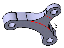
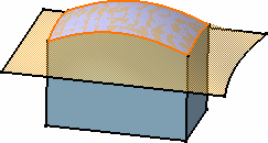
-
Double-click SewSurface.1 in the specification
tree to edit it and deactivate the Simplify geometry option.
-
Click OK.
The bottom of the solid is made of three connected faces. The smooth
edges resulting from the sewing appear because no topological
simplification has been performed.
|
|
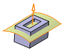
Using the "Intersect body" option
You will use the Intersect body option when the surface
straightly crosses the solid without being tangent. The application then
needs to compute the intersection between the surface and the solid, the
portions of surface with "free edges" being eventually removed.
Note that Intersect body should not be used in case of solids
having Through holes or pockets and where it is not possible for surface to
add material for sew operation. |
| |
 |
|
In the following
example, the application can compute the intersection: |
|
|
|
|
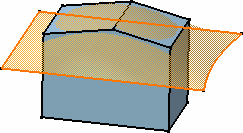
Checking
Intersect body in the Sew Surface Definition dialog
box automatically activates the Simplify geometry option. The
arrow indicates the portion of material that will be kept: |
| |
|
|
| The surface is sewn
onto the body. Some material has been removed. |
|
|
|
|
If you have a Cast and Forged Part Optimizer
license, you can also remove faces while sewing surfaces onto bodies. |
|
|
Modes of Deviation
This section provides you the information on deviation
modes to define the tolerance value.
While sewing the surface, you can define the deviation mode from the
Deviation list according to the required deviation limit:
- None: The tolerance is not applied. The
deviation is zero.
- Automatic: The maximum deviation value, that is 0.1, is
specified automatically and cannot be changed. By default, this
option is selected.
- Manual: In the Max Deviation box, the
maximum deviation value is specified manually in the range of 0.001 to
0.1.
|
|
|
- If the decimal places of the input value exceed the decimal
places defined at the Decimal places for read/write
numbers box, either the value rounds off or an error message
appears. For example, for three readable decimal places:
- If you enter 0.0001 in the Max Deviation box, an
error message appears.
- If you enter 0.00278 in the Max Deviation box,
the value rounds off to 0.003.
- You can enter the valid input or change the value of a readable
decimal number in Tools > Options > Parameters and Measure >
Units tab.
|
| |
Hybrid Design
When adding a surface-based feature or a surface feature
modifying another surface-based feature or surface belonging to the same
body, Part Design features based on that second feature then reference the
new added feature. In other words, a replace operation is automatically
performed. For an example, refer to
Creating Splits. |