|
When parts are far too complex for
finite elements analyses, there is a way of making them more simple. This
task shows you how to simplify a part by removing some of its faces. |
 |
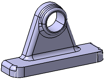
Open the
Update.CATPart document. As the Remove Face capability only
deals with the geometry of the part, not the history of its design, you can
use it for imported parts, like in the following scenario, or Version 4
parts. |
 |
-
Click Remove Face
 . .
The Remove Face Definition dialog box
appears.
-
Select the inner face as the face to be removed.
The face turns purple indicating that it will be
removed.
The following contextual commands are available from the
Faces to remove
field:
- Clear Selection:
removes all selected faces from the selection.
- Tangency Propagation:
includes all faces tangent to selected faces in the selection
- Fillet Propagation:
includes all tangent
continuous filleted faces of the selected face in the selection.
- Fillet propagation stops at sharp edges.
- The fillet propagation cannot be performed on
variable radius fillet.
|
|
|
-
Click the Faces to keep field and select both
faces as shown.
The faces turn blue, indicating that they will not be removed.
-
Check the Show all faces to remove option to
preview all the faces adjacent to the purple face that will be removed.
-
Click OK to confirm.
All of the faces have been removed. The new feature identified as
RemoveFace.XXX is added to the specification tree.
|
|
|
 |
If the operation takes longer than five seconds to complete, the
Update in Progress dialog box appears. In this case, do
one of the following:
- Wait for the operation to complete.
- Click Cancel to interrupt the operation.
|
You can change inputs in the Remove Face Definition
dialog box, to restart the remove face operation. |
|
 |
Create a Remove Face Feature Using Limiting Elements
|
|
|
You can partially remove some faces using limiting elements. This
particularly helps you to locally modify a fillet.
|
|
|
-
Click Remove Face
again and select the face as shown to remove it, in the Remove Face
Definition dialog box.
-
Click More>> to define limiting elements for
the removal of the face.
The Remove Face Definition dialog box dialog box is expanded:
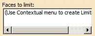
-
Right-click in the Faces to limit box and
select Create to determine a face to limit.
A new Faces to Limit dialog box appears.
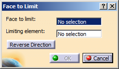
-
In the Faces to limit box, select the face
(shown in blue color) and in the Limiting element box, select the plane
as shown.
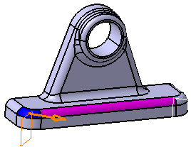
The arrow indicates the side of the face to be removed.
|
|
- You can click Reverse Direction or orange
arrow to reverse the direction of the face to be removed.
- The face to limit cannot be a removed face (Select the
Show all faces to remove check box to see which
faces are the removed faces).
|
|
-
Click OK to confirm the first limiting
element.
The orange arrow remains available on the limiting element. Thus, you
can change the orientation of the limiting element without editing it.
-
Repeat step 3 to 5 to create another limiting face as
shown.
|
|
The Faces to limit
box displays the following contextual commands:
- Edit: edits the limiting face created.
- Remove: deletes the selected face to limit.
- Clear all: clears all the
selections made.
|
|
 |
- In this command, you can select only one face to limit.
- The face to limit can only be split once.
|
-
Click OK to confirm the second limiting element.
The face is partially removed up to the limiting elements depending on
the defined direction. The new feature identified as RemoveFace.XXX
is added to the tree.
|
| |
More About Remove Face Features
Remove Face does
not create any new face. The capability is valid for existing topology
extrapolation. This is why the following pink face cannot be removed.
However, this one can be removed because there is a
possible trimming face that can be used by the application.
|
| |
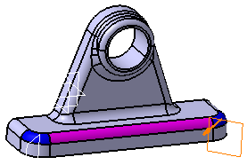
Self-Intersecting Volumes
The Remove Face capability may produce
self-intersecting volumes as illustrated in the following example:
Initial geometry
The 3D shape is composed of a shelled pad. Two fillets
(in lavender) were created on two of its edges.
Resulting remove face feature
Removing the internal fillet feature generates an
inconsistent shape.
 |
|
|
To analyze self-intersecting volumes, we recommend you
use the Split capability which most of the time provides a
better view of the problems:
 |
| |
Removing the appropriate face
By removing the external fillet first there is no
self-intersecting volumes, the resulting geometry is satisfactory.
|