-
Click Chamfer
 .
.
The Chamfer Definition dialog box appears. The default parameters to be defined are Length1 and Angle. You can change this creation mode and set Length1 and Length2. -
Select the edges to be chamfered.
Chamfers can be created by selecting a face: doing so chamfers its edges.
-
In the Mode list, select the desired mode:
- Length1/Angle (default mode, that is, an intersection of two normal lines which are perpendicular to each other): enter a length value and an angle value.
- Length1/Length2: enter two length values.

The Symmetric extent check box appears. Select it to define the same value for both lengths. When this check box is selected, the Length2 becomes unavailable. - Chordal Length/Angle: enter a chordal length
value (i.e. the chamfer width) and an angle value.
Width = Length / cos(Angle) - Height/Angle: enter a height value, that is
the distance between the intersection of the two adjacent
faces and the chamfer face, and an angle value.
Height = Length * sin (Angle) - Hold Curve/Angle: In the Hold Curve box, select the edge or the curve up to which the height of the chamfer is to be calculated and enter an angle value.
- Hold Curve/Length: In the Hold Curve box, select the edge or the curve up to which the height of the chamfer is to be calculated and enter a length value.
|
|
For creation of a chamfer using a hold curve, objects to chamfer and the hold curve must belong to the same 3D part. |
-
Optionally, click Preview to see the chamfers to be created.
The application previews the chamfers with the given values.
Propagation
Two propagation modes are available:
- Minimal: Edges tangent to selected edges can be taken into account to some extent. The application continues chamfering beyond the selected edge whenever it cannot do otherwise. In our example below, the chamfer is computed on the selected edge and on a portion of tangent edges:
- Tangency: The application chamfers the entire selected edge as well as its tangent edges. It continues chamfering beyond the selected edge until it encounters an edge that is non-continuous in tangency as shown in our example:
-
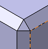
Select the Reverse check box to reverse the direction of the chamfer.
You can also click the orange arrow in the geometry. -
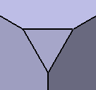
Select the Corner Cap check box to reshape the corner of the chamfered edges by capping it off.
With Corner Cap Without Corner Cap 
-
Click OK.
The specification tree indicates this creation. These are your chamfers: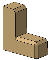
How Chamfers are Computed
The system uses the intersection of the two perpendiculars of the normal lines on supports to define the distances and angle values. The edge between the two surfaces is not used by the chamfer computation.
Chamfer Length-Length
Chamfer Length-Angle