-
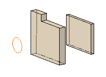
Select the circle as the profile to be extruded.

-
Click Pad
 .
.
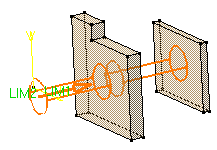
The Pad Definition dialog box appears and the application previews a pad with 10 mm as the default dimension value. -
Click the arrow in the geometry area to reverse the extrusion direction (or click the Reverse Direction button).
-
In the Type field, set the option to Up to last.

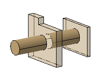
The last face encountered by the extrusion trims the pad.
Optionally, click Preview to see the result.

-
Click OK.
The pad is created. The specification tree indicates this creation.
![]()