 |
This task shows you how to
insert a Profile Contouring operation in the program. |
") |
Make sure that the pocketing
operation is the current entity in the program. |
 |
1. |
Select Profile Contouring
") . .
- The Profile Contouring dialog box appears directly at the
Geometry page
 . .
Make sure the Contouring mode is set to Between Two Planes. |
|
|
2. |
Click the Bottom: Hard text
in the sensitive icon to switch the type of bottom to Soft. |
|
3. |
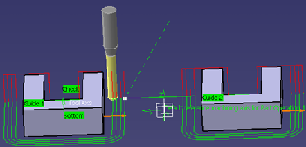
Click the Bottom plane then select the
corresponding part geometry (that is, the underside of the part).
The closed external contour of the bottom is proposed as Guide element
for the operation. |
 |
|
Make sure that the arrow on the Guide element is pointing
away from the part. |
|
4. |
Click the Top plane in the icon, then select
the corresponding part geometry. |
|
5. |
Double click Offset on Contour
in the icon.
Set this value to 1mm in the
Edit Parameter dialog box and click OK. |
|
|
6. |
Select the Strategy tab page
 and set the
parameters as shown. and set the
parameters as shown.
On selecting a check box, Side step First present in
the Stepover tab of the Strategy Panel, each disconnected guide would be
handled individually by the profile contouring operation for all the
passes and then the tool would move to the next guide to perform all the
passes.
By default, this option would be selected for newly created operations.
On selecting the check-box, the functionality would be applicable for
Radial as well as Axial strategy, and would store the settings in a file
which would be available for the next operation.
If the guides are not disconnected and you select this option, there
would be no change in the current behavior. The tool path would be the
same as in it without this option for connected guides.
Previously, if you have given more than one pass to machine, then all
the guides for the first pass will be machined, then the second pass
would be started which would again involve all the guides. This
approach involved alot of connecting motions between the disconnected
guides and unnecessary machine time is consumed. With this
functionality, it is
unnecessary connecting motions (in red color) that are generated and
each guide is machined for the first pass and then each guide is
machined for the second pass and so on.
If you want to machine one guide completely and then move to the next
guide, then previously the only way available presently is to create
separate operations for each guide.
|
|
7. |
If needed, you can change the tool axis orientation. Just
click the Tool Axis symbol then click the Reverse Direction
button in the Tool Axis dialog box.
You can display the tool with
the specified orientation by selecting the Display tool check box.
|
|
8. |
Click
Preview in the dialog box to
request that the program verifies the compatibility of the selected tool,
geometry and machining parameters. A message box appears giving feedback
about this verification. |
|
9. |
Click Replay in the
dialog box to visually check the operation's tool path. |
|
|
 At the end of the replay
click OK to return to the Profile Contouring dialog box. |
|
10. |
Click OK to create
the operation. |
|
 |