|
|
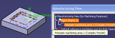
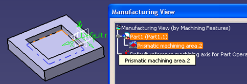
This gives you the capability to identify a Prismatic Machining Area feature visually in 3D Viewer by moving the cursor over feature or selection in the Manufacturing View. This also gives you the capability where the system would add representations of Prismatic Machining Area Features and Machinable Axial Features in 3D Viewer. You can identify and select features from 3D Viewer and use them directly in these operations. | |
|
|
1. | Select the geometry of Guiding elements of
Prismatic Machining Area features
that could be used. It is pre-highlighted. The Guiding element geometry could be faces or
edges.
The faces.
The edges. |
|
|
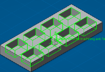
With this, the permanent
representations of Prismatic Machining Area and Machinable Axial Feature would be
added onto the recognition of the feature. Initially these representations
are hidden. Make them visible by selecting the Show from the Hide/Show option in the contextual menu of the features in the Manufacturing View or make all features visible by holding the CTRL button down, while selecting. 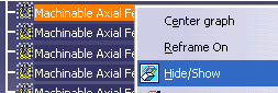 The following representation
elements can be used for permanent representations of a Machining
Pattern. The green color would be used for permanent representations of
a Machining
Pattern. |
|
| 2. | The entry point (hole origin) and entry
vector (hole direction) of the axial feature would be used for permanent
representations (green color) of Machinable Axial Features.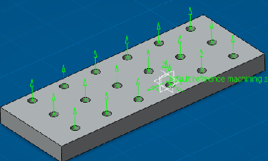 Geometry of Guiding elements of Prismatic Machining Area feature would be used for a permanent representations. |
|
 You can use these permanent representations for selecting a feature directly from 3D Viewer. This can also locate respective features in Manufacturing View from the 3D Viewer through these representations. |
||
| 3. | Permanent representations of
Machinable Axial Feature in 3D Viewer can be selected through
clicking on the existing command NO point in the geometry tab panel of
Manufacturing Axial Operations dialog box. 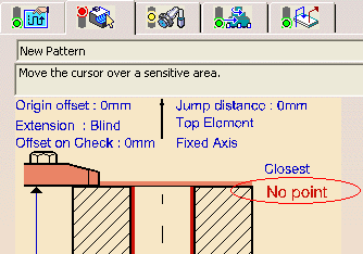 |
|
| 4. | You can use this command in geometry panel
of Pocketing and Profile Contouring operation for selecting permanent
representations of Prismatic Machining Area feature from the 3D Viewer.
Select Prismatic Machining Area
feature by clicking on
NOTE: In Machinable Pattern you can create machining patterns in two
ways. |
|
| 5. | Select the Counter Depth in the
Pattern tab of GFT and the Pattern Creation panel.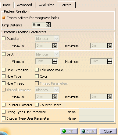 When selecting this option Counter Depth and create machining patterns the counter depth of Machinable Axial Features is taken into account for the Pattern Creation. |
|
|
|
||