-
With your document open click the Generate ISO button
 . in the
Detailing Tools toolbar.
. in the
Detailing Tools toolbar. The Generate ISO dialog box displays. 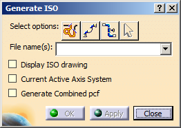
-
The select options buttons allow you to select what
you want to convert.
Click the Select Line IDs button to select by line ID. When you click this button a dialog box
will display all line IDs available to you, from which you can make your
selection. Everything belonging to the line ID will be converted.
button to select by line ID. When you click this button a dialog box
will display all line IDs available to you, from which you can make your
selection. Everything belonging to the line ID will be converted. -
Click the Select Spool
 button to select by spool.
When you click this button all spools available to you will be displayed. Select one or more. Everything belonging to the spool(s) will be converted. -
Click the Select Element
 button to select a range.
When you click this button, the Analyze Networks dialog box will display.
-
Click the Network tab and then an object in your document. All objects connected to it will be selected and the name of the object will display in the Selected Object field. All objects connected to the selected object will be converted.
You can also select a range within your document. To do this click the Path tab in the Analyze Networks box, select the first object in your range (its name will display in the From Object field) and select the last object in your range (its name will display in the To Object field). It is better to select the objects in the specifications tree, but you can select in the viewer also. All objects within the range will be converted.
-
The Select Support Parts
 button
is grayed out until you make a selection. Support parts like hangers and
sleeves may not be included in your selection and this button allows you to
select them. To give an example, if you select a spool, then support
parts are frequently not part of the spool. To use it, select a spool
(or any other selection) and click the Select Support
Parts button. If a support part shows, but is not
included in the selection, click the part. The part will be included when you
generate a drawing. If you click a selected support part a second time
it will be de-selected.
button
is grayed out until you make a selection. Support parts like hangers and
sleeves may not be included in your selection and this button allows you to
select them. To give an example, if you select a spool, then support
parts are frequently not part of the spool. To use it, select a spool
(or any other selection) and click the Select Support
Parts button. If a support part shows, but is not
included in the selection, click the part. The part will be included when you
generate a drawing. If you click a selected support part a second time
it will be de-selected. - Enter a file name for the
isometric drawing and press Enter when you are using the Select Elements
options.
In other cases a default file name will be generated for the drawing, but it is best to give your own file name because default file names can confuse. If you are converting everything belonging to a line ID, for instance, the file name will be that of the line ID. If you perform the step again the application will create a second file with the same name and the letter "A" (or whatever sequence it is) attached.
-
Select the Display ISO drawing check box if you want to see the drawing when it is generated. If you do not select the check box, the drawing will be stored and you can view it later.
-
Optional: Select the Current Active Axis System check box to measure all dimensions with reference to the current active axis system.
-
Optional: Select the Generate Combined pcf check box to generate a single pcf file for two or more line IDs used in the design.
-
Click OK to generate the drawing.
The Converting Data window will display progress.
When the drawing has been generated, the New Drawing dialog box displays. Select any of the options you want and click OK.
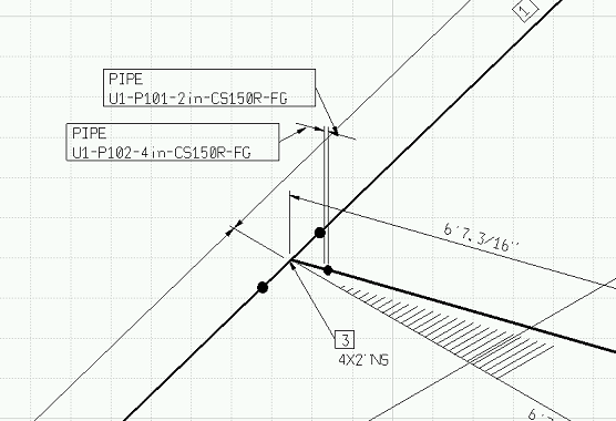
- If you had checked the
Display ISO
Drawing option then the drawing will display. It will contain various kinds
of information and will display dimensions. You can change unit dimensions
by going to the ISOGen Setup tab described in
Setup Requirements.
- A large drawing will be split into manageable sections and only the first section will display initially.
- If the Generate Combined pcf
check box is selected, and you click OK to
generate the drawing is created the attributes of each line
ID is displayed in drawing.
- If the line IDs are connected, a combined drawing and a combined pcf file is created.
- If the line IDs are not connected, different drawing are created for each line ID. However, there will be a combined pcf file for all the line IDs.
- The naming convention for the combined pcf file is Combined_xxx_yyy.pcf and for combined drawing is Combined_xxx_yyy.dxf. Here, xxx and yyy stand for the corresponding selected line IDs.
- If you had checked the
Display ISO
Drawing option then the drawing will display. It will contain various kinds
of information and will display dimensions. You can change unit dimensions
by going to the ISOGen Setup tab described in
Setup Requirements.
-
To view the drawing later click the View ISO Drawing button
 in
the toolbar. A window will open at the Drawings directory. This is a
subdirectory of the Style directory you created earlier.
in
the toolbar. A window will open at the Drawings directory. This is a
subdirectory of the Style directory you created earlier.