- Show/Hide,
- Low intensity/High intensity,
- Color and transparency.
Go to Tool > Options > Mechanical Design > Mold Tooling Design, then to the Viewer Mapping tab to customize the lists of functions and elements shown in the Tool Viewer.
-
Select Tools >
 Tool Viewer.
The Tool Viewer dialog box is displayed:
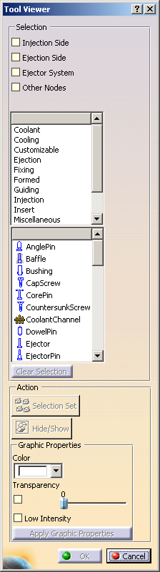
You must first define selection criteria as explained below.
Clear Selection lets you reset all the selection criteria (nodes, functions and types) whenever you want. -
Select at least one node to explore:
-
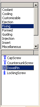
You can select one or several function criteria from the list.
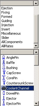
In the list below, only the tooling element types corresponding to the selected functions are displayed and are selectable.
By default, they are all selected.
-
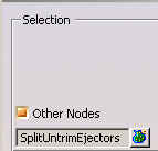
You can also select tooling element types without selecting a function.
The tooling elements corresponding to the selection criteria are highlighted in the specification tree and in the 3D viewer. You can define an action, as explained below. -
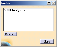
- Enter the name of the selection set in the dialog box
that appears and click OK.
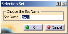
A selection set is created with the tooling elements that meet the selection criteria.
- Enter the name of the selection set in the dialog box
that appears and click OK.
-
Click Hide/Show.
The tooling elements that meet the selection criteria are hidden.
Click Hide/Show again to redisplay them. -
Change the Graphic Properties of the tooling elements that meet the selection criteria:
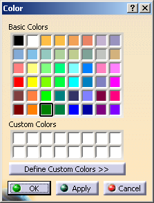
- Select a color, More Colors, or No Color
from the list.
More Colors starts the color editor.
- Select the Transparency check box, and define its level with the slider.
- Select the Low Intensity check box.
- Click Apply Graphic Properties. The changes you have defined are applied to the tooling elements that meet the selection criteria.
- Select a color, More Colors, or No Color
from the list.
-
Click OK to validate your changes and exit the dialog box, or click Cancel to exit the dialog box without keeping any modification.
In this release, Undo/Redo is not available.
![]()