 |
Before you can run this procedure, take the following
steps:
-
On the Tools > Options > Machining > Output
tab,
select a Post Processor type for your NC code (e.g.,
ICAM).
-
On the Tools > Options > Machining > Output
tab,
in the Default File Locations area, specify CATNCCode as the
file extension, and select output locations.
-
Assign an NC machine to the part operation.
-
In the machine editor dialog box for the NC machine
(accessible in NC Machine Tool Simulation by right-clicking the machine
on the PPR tree, and selecting machine object > Edit), set
the Controller Emulator, Post Processor, and
Post Processor words table appropriate for your machine and the
Post Processor you selected in Step 1.
 |
 |
The contents of the lists available on the machine editor
dialog box depend on the options selected in Tools > Options >
Machining > Output. |
|
 |
-
Double-click on the Manufacturing Program in the PPR
tree.
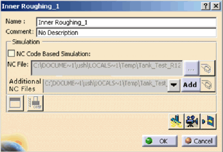
| The program dialog box appears (the name of the
dialog box is the name of the manufacturing program, e.g., 001). |
 |
 |
If your options are set as described above, you
can simply right-click on the manufacturing program, and select
Simulate Machine using NC Code. |
 |
Click the Add button on
Additional NC Files to add controller-specific
sub-programs or continuation file to this list. Normally, these
are not generated by the Post Processor. |
 |
If you want to modify the workpiece origin or cutter
compensation data before running the simulation, see
Managing Specific NC Codes. |
-
Click Start Machine Simulation
 . .
 |
For more general information on running simulations, please see
Viewing a Simulation.
|
| Depending on whether you have created any kind of
simulation with this process before, you may see the following
warning: |
 |
| If you receive the above warning, click the
Yes button. |
| The processing of the simulation may take some
time. Depending on the post processor you selected, you may
see a progress bar window in your task bar. |
| The Process Simulation toolbar appears. |
 |
-
Click Run
 . .
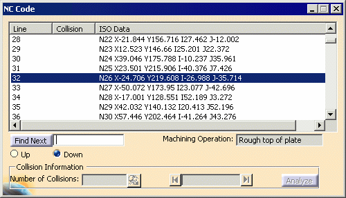
| The NC Code dialog box appears. |
 |
 |
While the simulation is running, the dialog box shows the line and
Machining Operation affected. Once the simulation
is complete, select the X (close) button on the Process
Simulation toolbar. The Process Simulation
toolbar disappears, and the NC Code dialog box can be used for collision checking and analysis. You
can also select a subset of sequential lines of code to run a
partial simulation. Tool path display is not applicable for NC Code
simulation.
|
| |
If you are running a subprogram it has its own ISO (NC
Code) dialog box which gets updated with the simulation. When
simulation is happening for the Isubprogram, both the main and
sub-program dialog box are visible. Once the control returns to the
main program, the NC Code dialog box for the subprogram disappears.
In case of multiple subprogram calls, only the main NC Code
dialog boxand the active subprogram’s NC Code dialog
box are visible.
i.e., all the transient NC Code dialog box are hidden. |
 |
For more information on the features of the NC Code
dialog box, see
About the NC Code Dialog Box. |
|
![]()