Specify user parameter name, if you want to create machining pattern on the criteria of User parameters.
A check box Counter Depth is added, to take the counter depth of the Machinable Axial feature into account while creating patterns.
You can enter the name of User parameter that needs to be used for reading the parameter from axial features for Pattern creation. You can select a single parameter or both the parameters together and enter their names. You can specify the name of only one parameter in one text box.
You can create patterns based on only String type parameter, only integer type parameter, or combination of both the parameters. You can use these parameters in conjunction with other options already present for pattern creation.
Name of these parameters are case independent. For string parameters comparison is based on the string value of the parameter. This comparison is case insensitive. Any pattern created using this criterion have the String value of the String type parameter suffixed with the Pattern name.
For integer parameter comparison is based on the integer value of the parameter. Any pattern created using this criteria have the Integer value of the Integer type parameter prefixed with the Pattern name.
If you have selected the check box for string/Integer type as the criteria to create pattern and left the text field as blank or did not input the correct name then while pattern creation that criteria would not be followed. For this no error or warning message would be shown at the time of pattern creation.
By default both the options remain disabled and the selection preference of both the check boxes is saved in setting. The values entered by the you in the Name text box is not saved in the setting.
To see all the included parameters and their value, Refer to Display of User Defined Parameters.
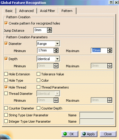
With these parameters you will create a pattern on threaded holes whose diameter is included in a specified range of diameters (that is, between 17 and 20mm).
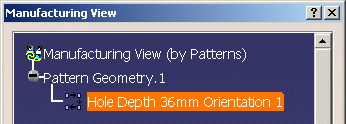
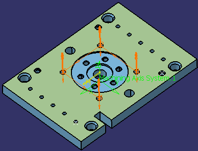
The created machining pattern is displayed.
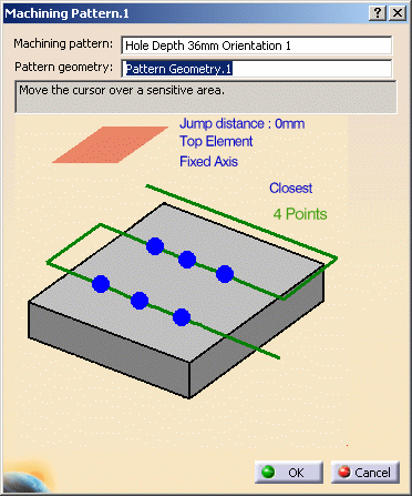
Geometry Considerations for Pattern Creation
Pattern creation operates on a set of axial features selected from the Manufacturing View, a set of faces, or an entire body.
- For a set of axial features, pattern creation applies the matching criteria only to that set of features.
- For a set of planar faces, pattern creation applies
the matching criteria to all axial features from each face
in the set. Note that all features in a pattern have
identical axes.
If a reference direction is defined, the matching criteria only applies to machinable axial features parallel to this axis. - For a set of non-planar faces, pattern creation applies
the matching criteria to all axial features from each face
in the set. Features in the pattern can have different axes.
If a reference direction is defined, automatic pattern creation only applies to machinable axial features parallel to this axis. - For a body, pattern creation applies the matching criteria
to all axial features. Note that all features in a pattern
have identical axes.
If a reference direction is defined, automatic pattern creation only applies to machinable axial features parallel to this axis.
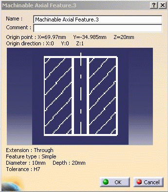
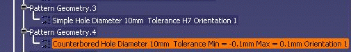
Using Tolerances in Pattern Creation
You can retrieve the fitting tolerances defined in design features when machinable axial features are created. You can match these tolerance values in the pattern creation functionality.
The Tolerance Value check box for matching the fitting tolerance for pattern creation.
You can create patterns of holes having same tolerance values.
Matching is done for both tabulated (H7, and so on) as well
as minimum/maximum tolerance values.
Features having the same tolerance values are grouped in the
same pattern. Other holes, for which the tolerance value is
not defined, form a separate pattern.
The fitting tolerance value is retrieved and information is displayed to user:
- in the dialog box of the Machinable Axial Feature:
- in the Manufacturing View on the created pattern:
Pattern Creation with Color Criteria
When you select the Color check box for pattern creation, colors of holes are matched for creating patterns. The color of the machining axial feature faces is taken into account for pattern creation. This color may be a basic color or a RGB color (Red, Green, and Blue value).
Note that all holes have a color. When no specific color is defined on the faces, the face color is the same than the body color.
- If only the Color check box is selected then
all the holes with same machining axis and having same color
form a pattern.
This behavior is similar to other pattern creation options. For all the pattern creation options a created pattern have holes with same machining axes.
Exception to this is holes having non-planar top faces.
When there are some holes having non-planar top faces and if none of the holes have the axis same as any of the planar holes, then these holes can form a single pattern even if their axes do not match. - If other criteria are also selected along with color then holes matching all the other criteria and color form one pattern.
- If only color is selected and machining direction is specified, then all the holes having axis parallel to machining direction and having same color form one pattern. Holes, which do not have axis parallel to machining direction, does not form any pattern.
- If the holes have more than one color, these holes come under a separate pattern for that specific orientation.
Example:
Part with counterbored holes (same hole and counterbored diameters):
10 counterbored without specific color
10 counterbored (all faces in red)
10 counterbored (first diameter face in blue, second diameter face in red, other faces without specific color).Hole with more than one color is taken into account in a specific pattern.
Three patterns get created:
- pattern for the undefined color (10 holes)
- pattern for the red color (10 holes)
- pattern for the holes with more than 1 color (10 holes).
Note: If you haveselected the color option for pattern, RGB color definition is added at the end of pattern name as Color (R value, G value, B value).
![]()