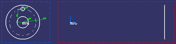
Create a left projection view from the existing front view.
Project 3D Elements
-
Double-click the left view to activate it.
-
Click Project 3D Elements
 in the 3D Geometry toolbar or select Insert > 3D
Geometry Use Edges > Project 3D Elements from the menu bar.
in the 3D Geometry toolbar or select Insert > 3D
Geometry Use Edges > Project 3D Elements from the menu bar.

-
Select the element to be projected. For the purpose of our scenario, select the bigger circle in the front view.
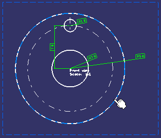
The edge is projected onto the left view plane.
Project Using Select Boundary Edges
-
Select the faces of interest.
-
Right-click on the selected face(s) and select Select Boundary Edges from the contextual menu.
The selected faces are highlighted in red color. -
Click Project 3D Elements
in the 3D Geometry toolbar.
The selected boundary edges are projected on the plane. Unlike in the Sketcher workbench, the creation of marks is not listed in the specification tree.
More about projecting 3D elements
When projecting 3D elements, remember the following points:
- The element to be projected can be either a 3D face, an edge or a vertex. It cannot be a body.
- Selecting a face results in selecting its boundary edges.
- The projected geometry is created in the current view.
- The projected geometry is not necessarily a single element; distinct elements are created corresponding to each selected edge or vertex.
- If the selected element is invalid or if the projection is not properly performed, an error message is displayed.
- Be careful when multi-selecting a mix of 2D and 3D elements to project. In this case, 2D elements are projected only if they are located in the view background; in other words, any 2D element located in the foreground of the view will not be taken into account.