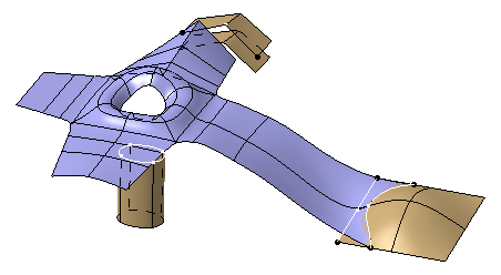
- Create a 3D shape containing a subdivision surface.
- Create a boundary curve.
-
From the Operations toolbar, click Creation Match Surface
 .
. -
Select the edge of a subdivision and then select the boundary curve.
-
Click Apply
 .
.A matching constraint between the two geometrical elements is created.
-
From the Tools Palette, select any one of the following:
Option Description  Modification
Selects the matching constraint to be edited.  Remove
Removes the selected matching constraint.  Remove All
Removes all matching constraints.
Creation Match SurfaceCreates a new matching constraint.  Target Selection
Selects the boundary curve of a matching constraint.  Tangent Propagation
Propagates the selected edges in tangency.  Sharp to Smooth
Chooses between a very sharp matching surface, or a smooth and curved matching surface. Click Sharp to Smooth
to switch
to Smooth to Sharp
 .
. Deform
Adds a new ribbon of faces to lower the deformation of the original surface. Click Deform to switch to Add.  Automatic or Custom Options
Provides additional options.  Cut
CutDefines the number of cuts on your matching surface.  Ratio
RatioSpreads the deformation created by the match.  Connection Quality
Defines the connection quality and continuity of a matching surface.  Curvature Quality
Defines the curvature quality and continuity of a matching surface.  Mesh View
 Hides or displays the base mesh.
ApplyValidates the command.

- You must click Apply
each time you use an option.
- You do not need to create a curve on a surface to make a matching constraint.
- You can only use the Sharp
to Smooth
option if you create a matching constraint with a curve that
does not lie on a surface.
- You can work in automatic mode for a more efficient use of the options.
- You must click Apply
-
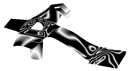
From the Analysis toolbar, click Isophotes Mapping Analysis
 .
. -
In the Isophote Mapping Analysis dialog box, select Analysis mapping on part or element by element
 .
.This option lets you analyze the quality of the matching constraint you have applied.
-
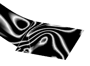
From the Tools Palette, click Curvature Quality
and use the slider to modify the reflection quality of your matching
surface as desired.
![]()