-
Click Symmetric Zone
 in the Operations toolbar.
-
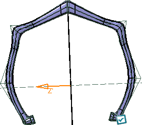
Select the subdivision surface.
|
A Tools
Palette is displayed. |
-
Select the faces to constrain and the symmetry plane.
The symmetry plane is located at the bar center of the
selected elements. No vertex is modified and the subdivision
surface remains unchanged.
| The following icons are displayed in the tools
palette: |
-
 Reset All Constraints: Resets all symmetric zone
features.
Reset All Constraints: Resets all symmetric zone
features.
- The following commands let you constrain the
symmetry zones:
| |
-
 Select First Zone: Selects first
zone.
Select First Zone: Selects first
zone.
-
 Select
Second Zone: Selects the zone
symmetric to the first zone.
Select
Second Zone: Selects the zone
symmetric to the first zone.
-
 Select
Whole Zone: Selects the
set of faces to constrain
Select
Whole Zone: Selects the
set of faces to constrain
-
 Select
Cutting Edges:
Defines cutting edges. Selecting one
edge is enough, a propagation defines
through the set of faces the symmetry on
the right and on the left of the edge
frontier.
Select
Cutting Edges:
Defines cutting edges. Selecting one
edge is enough, a propagation defines
through the set of faces the symmetry on
the right and on the left of the edge
frontier.
|
 |
The two selected zones must have the
same number of faces and edges. |
-
 Symmetrize Whole Mesh:Performs a
symmetry on the whole mesh.
Symmetrize Whole Mesh:Performs a
symmetry on the whole mesh.
| |
-
 Define Robot Plane: Modifies the origin
and orientation of the Robot and exits the robot definition to return to
the previous function.
Define Robot Plane: Modifies the origin
and orientation of the Robot and exits the robot definition to return to
the previous function.
-
 Reset Robot: Resets the orientation of
the Robot to the model axis.
Reset Robot: Resets the orientation of
the Robot to the model axis.
-
 Selection:
Activates the plane selection. Selection:
Activates the plane selection.
-
 Plane Translation: Translates the plane.
-
 Plane Rotation: Rotates the plane.
|
-
 Symmetrize selected
faces: Performs a symmetry on the selected
faces. The Switch Symmetry Side
Symmetrize selected
faces: Performs a symmetry on the selected
faces. The Switch Symmetry Side
 Switch Symmetric Side: Lets you select the side to keep.
-
 Apply Mean Symmetry: Performs a symmetry at the mean plane between the
selected elements.
Apply Mean Symmetry: Performs a symmetry at the mean plane between the
selected elements.
|
|
Symmetrize Selected Faces and
Apply Mean Symmetry are available
when the selection is symmetric to the plane |
-
 All Elements Selection:
Selects all elements.
All Elements Selection:
Selects all elements.
-
 Apply (Enter):
Applies the command.
Apply (Enter):
Applies the command.
|
|
|
|
-
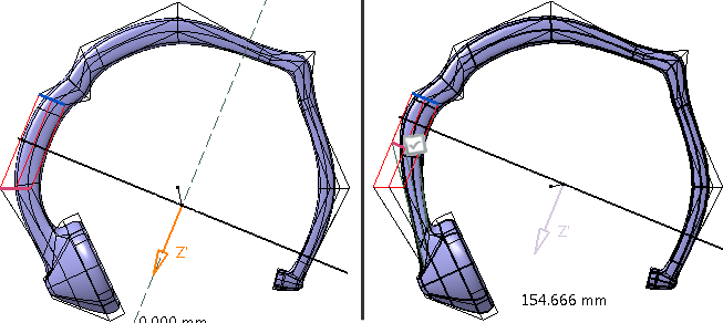
To constrain the two zones:
| |
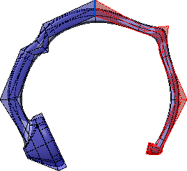
- Click Select First Zone
and select the first zone.
The selection is displayed in red.
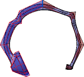
- Click Select Second Zone
and select the second zone.
The selection is displayed in red.
|
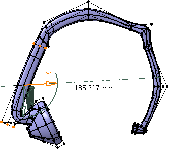
-
Use the arrow to translate the mesh.
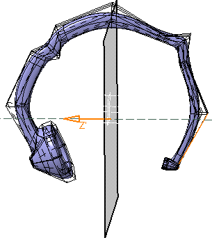
-
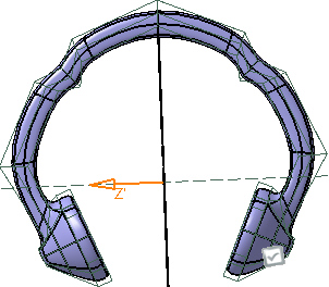
Click Symmetrize Whole Mesh
.
The whole mesh is symmetrized.
In the tools palette, click Switch Symmetry Side
to switch the side to keep.
-
Select several elements and click Symmetrize
Selected Faces
.
All the selected elements of the mesh are symmetrized.
-
Click Apply
to apply the changes.
The Symmetric Zone.x feature is created in the
Subdivision Surface.x node in the specification tree.
-
From the Modification toolbar, select
Modification
 .
.
-
In the Tools Palette, click Translation
.
-
Select a point in the zone and translate it.
The selected point and its symmetric element are both translated.