-
Click Modification
 and select the surface.

You can also access this command by pressing SPACE. -
Click Alignment
 .
.You can also access this command by pressing CTRL+SHIFT+Q. When the Alignment command is activated, four new icons appear in the Tools Palette:

The following icons let you: -
 Align
Vertices on an Axis of the compass.
Align
Vertices on an Axis of the compass.
-
 Align
Vertices on a Plane of the compass.
Align
Vertices on a Plane of the compass.
-
 pick
one or more 3D elements in the 3D area to define the projection support.
pick
one or more 3D elements in the 3D area to define the projection support.
Note: It is available with the Orthogonal and Along Direction options.
The other icons let you filter the type of aligning feature: surface, edge or vertex. -
-
Click Compass Definition
 to define the position of the compass as required.
-
Click Compass Definition
again.
Align Vertices on an Axis
-
Click On Axis
.
When this option is activated the following options are available for surface selection: Edge Selection, Vertex Selection, All Elements Selection. -
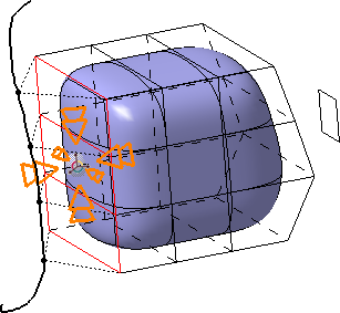
Select elements to be projected.
The manipulator arrows are displayed on each axis.
The manipulator is active when you are in the picking zone. You can click anywhere in the picking zone for modification.As you are in the picking area of the manipulator, the projection axis and traces of projections are viewed. This axis size is defined to include all the projected points. The direction of the interactive arrows is normal to the plane.
-
Click the manipulator arrow depending on the direction where you want to align the vertex.
The selected elements are projected on the axis.
-
You can also align the elements on the axis using
two positioning modes.
- Not Uniform
 :
The distribution of the elements is not uniform.
:
The distribution of the elements is not uniform.
- Uniform
 :
The distribution of the elements is uniform.
:
The distribution of the elements is uniform.
- Not Uniform
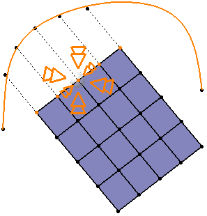
Align Vertices on a Plane
-
Click On Plane
.
When this option is activated the following options are available for surface selection: All Type Selection, Face Selection, Edge Selection, Vertex Selection, All Elements Selection. -
Select elements to be projected.
The manipulator arrows are displayed on each axis.
The manipulator is active when you are in the picking zone. You can click anywhere in the picking zone for modification.
As you are in the active manipulator zone, the projection plane and traces of projections are viewed. This plane size is defined to include all the projected points. The direction of the interactive arrows is normal to the plane. -
Click the interactive arrow depending on the direction where you want to align the vertex.
The selected elements are projected onto the plane.
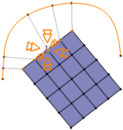
Align Vertices on a Circle
-
Click On Circle
 .
. -
Select elements to be projected.
The manipulator arrows are displayed on each axis.
The manipulator is active when you are in the picking zone. You can click anywhere in the picking zone for modification.
When you are in the active manipulator zone, the projection circle and traces of projections are viewed. This circle size is defined to include all the projected points. The direction of the interactive arrows is normal to the circle. -
Move the pointer over the interactive arrows to visualize the projection circle in different planes. Click the interactive arrow depending on the direction in which you want to align the elements.
You can change the radius of this circle, by moving the manipulator inward or outward before releasing the pointer.
The selected elements are projected on the plane.

Note: You can position the elements to be aligned on a circle. The following three positioning modes are available: - Not Uniform
:
The distribution of the
elements is not uniform.
- Uniform
:
The distribution of the
elements is uniform. All the
elements are positioned at an equal angular distance from each
other on the whole circle.
- Uniform Arc
 :
The distribution of the elements is uniform. All the elements are
positioned at an angular distance equal from each other on an
arc of circle defined by a start and an end point.
:
The distribution of the elements is uniform. All the elements are
positioned at an angular distance equal from each other on an
arc of circle defined by a start and an end point.
- Not Uniform
Align Vertices on a Support Element
-
Click On Body
 .
.
When this option is activated the following options are available for surface selection: All Type Selection, Face Selection, Edge Selection, Vertex Selection, and All Elements Selection. -
Select elements to be projected.
-
Select the support element.
The manipulator is displayed with a sphere in its middle.
Note: You can also click Drawing  to draw the support element.
-
Move the mouse over:
- The center of the manipulator to display arrows on each
axis. Click anywhere in the picking zone to perform an
orthogonal projection.
Projection traces are previewed. - The interactive arrow corresponding to the direction
where you want to align the vertex to perform a projection
along a direction.
The direction of the interactive arrows indicates the direction of projection and is normal to the support surface. Projection traces are previewed.
Note: You can click on an arrow and move the mouse towards the geometry to perform an exact alignment.
The selected elements are projected onto the support element:
Orthogonal projection:
Projection along a direction:
- The center of the manipulator to display arrows on each
axis. Click anywhere in the picking zone to perform an
orthogonal projection.
-
From the Tools Palette, select any of the projection commands.
-
Press Alt and move the pointer over either of the following elements:
- The handle arrow displayed on each axis.
- The center of the handle to perform an orthogonal projection.
Without Alt pressed:
With Alt Pressed:
Associate Aligned Vertices
-
Click On Body
. -
Select elements on the subdivision surface to be projected.
-
Select the feature on which the selected elements are to be projected.
- Click anywhere in the picking zone to perform an orthogonal projection, or
- Select the interactive arrow corresponding to the direction where you want to align the vertex to perform a projection along a direction.
-
The icon
 appears in the Tools Palette.
 -
Click Associate
.- An association is created between the subdivision surface and the feature.
- A symbol is displayed on the subdivision surface icon in the specification tree denoting the association.
-
Now if the feature is modified, say by translation,
the associated elements of the subdivision surface are also modified
accordingly.
-
Ctrl and Shift keys are used for selection. When these keys are pressed, the manipulator is inactive even in the active manipulator zone.
-
In case of element selection, manipulators can be deactivated by keeping the Ctrl key pressed. This allows better selection of elements. To reactivate the manipulators, release the Ctrl key.
-
If no element is selected for the projection, the manipulator is inactive even in the active manipulator zone.
-
The manipulator's active picking zone is located between two virtual circles (red and yellow circles). Thus it is not possible to manipulate the manipulator near the axis (yellow circle) and outside the red circle.
-
The display of the projection plane depends on the option selected for transparency in Tools > Options > Display > Performance tab, Transparency Quality area. The options are:
-
Low (Screen Door)
-
High (Alpha Blending)
For more information on these options, see CATIA Infrastructure User's Guide: Customizing: Customizing settings: Performance.
-
-
The visualization of hidden elements depends on the state of View and Selection mode
 icon
in the Operations toolbar. For
more information, see Selecting
Visible Elements.
icon
in the Operations toolbar. For
more information, see Selecting
Visible Elements. -
It is not possible to project a face or an edge onto an orthogonal edge. An error message is displayed.
-
It is not possible to project two opposite edges of the same face onto a common axis. A similar error message is displayed.
![]()