-
Click Face Cutting
 in the Styling Surfaces toolbar.
You can also access this command by pressing ALT+SHIFT+F. -
Select the surface to be cut.
-
Click Cut Multi-Edges
 ,
if not already selected.
,
if not already selected. -
Drag the slider to the number of desired sections.
-
Select the edge to be cut.
You can also click
 above the slider
to open the Number Of Sections dialog box and define the
number of sections between 1 and 9. The field dynamically updates
whenever you move the slider and vice-versa.
above the slider
to open the Number Of Sections dialog box and define the
number of sections between 1 and 9. The field dynamically updates
whenever you move the slider and vice-versa.
-
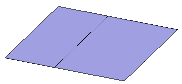
Cut the surface as required.

The section insertion propagates to the connected faces. -
Now, click
Cut Manipulation
 .
.
A new slider is displayed on the screen to let you position the sections using a ratio (the ratio value depends on the number of sections you have previously defined). - Drag the
slider to the desired ratio.
The position of the sections moves on the surface:
- You can also
above the slider
to open the Cut Ratio dialog box and define the
ratio. The field dynamically updates whenever you move the
slider and vice-versa.
- If the number of sections has been set to 1 and only one
edge has been selected, positioning the section can directly
be defined by picking the selected edge:
A second click on the edge allows you to position the section and validate the command.
- To deselect an edge, press Ctrl and click the edge.
- You can also
- Click
Apply
 to
validate every cut you make or use the Crtl key to multi-select the cut
surfaces and then click Apply.
to
validate every cut you make or use the Crtl key to multi-select the cut
surfaces and then click Apply.You can also validate by reselecting the same element again. This information is given in the help text when in detailed mode along with
icon in geometry and the pointer changes to
 .
In case a element can be
validated
but is not active the
.
In case a element can be
validated
but is not active the
 icon is seen and the pointer is not changed.
In the Modification toolbar, click Multi-Selection  to validate the current operation and select the next
surface to cut without exiting the Face Cutting
command.
to validate the current operation and select the next
surface to cut without exiting the Face Cutting
command.
You can also press Ctrl +Space to validate the current operation and select the next surface to cut.You can see that the surface is cut.
-
During the command execution the selected elements are previewed on the surface.
-
The command is executed, only after the selection is validated using Apply (Enter) command.
-
Apply is automatic applied before quitting the command.
-
When the modification is not possible, the Apply icon is not active.
-
You can undo or redo the changes only after the completion of command; after the Apply command. Intermediate selection states cannot be managed by undo/redo.
-
- To quickly cut
the face, click Cut on click
 .
.
A sphere appears as you hover over the edge.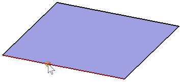
- Click at the required location to cut the face.
-
An interactive zone is defined around the slider. When you are in this zone, the pointer position allows to preview the value which is highlighted. A click moves the slider cursor directly to the highlighted value position.
-
Click and drag the pointer in the interactive zone, so that the slider cursor moves on the slider highlighting the value.
-
-
When the cursor is on a value, the value is displayed with more thickness than others for easy identification.
-
The slider can be customized using the anchor point circle at the lower end of the slider. Drag this point across the screen. The preview of the location where the slider can be dropped is displayed. The slider automatically changes its shape according to its position horizontal, vertical or corner.
-
The slider can be scaled using the resizing manipulator on top.
![]()