Extruding Edges Using Directions

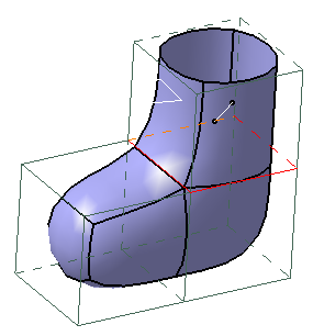
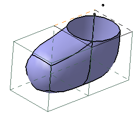
Extrude Edges Along Local Directions

Open the Extruding4.CATPart document.
  1. In the Tools Palette, click Extrusion .

  2. Press Ctrl and select multiple edges.

    Along an edge:
    With a corner:
    All edges:
   

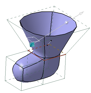
Extrude Edges Using a Fixed Direction

 
  1. In the Tools Palette, click Extrusion Fixed Direction .
    You can also access this command by pressing Ctrl + Shift + B.

  2. Click any one of the following:

    Command Description Shortcuts
    Select Direction Enables you to select a direction from the elements of the mesh.  Ctrl + Shift + D
    Pick Enables you to select an existing element to define the direction.
    Note: Select an element that does not belong to the subdivision surface.
    Ctrl + Shift + K
    Invert Extrusion When a direction is defined, it inverts the side of the extrusion. Ctrl + Shift + I
    Attraction Enables you to add weight on the junction with the extruded elements.  Ctrl + Shift + F
    Smooth to Sharp Defines the continuity type on the junction with the extruded elements (if a weight is defined). Click Smooth to Sharp to switch to Sharp to Smooth . Ctrl + Shift + H

  3. Click Select Direction and select the required direction.

  4. Press Ctrl and select multiple edges.

  5. To modify the direction according to an element, click Pick and select an element.


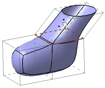
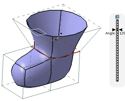
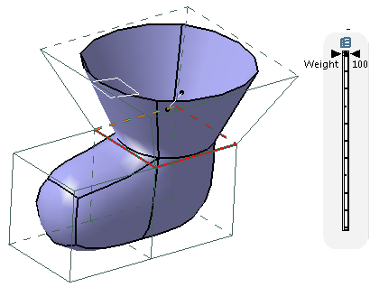
Extrude Edges Using a Direction and an Angle

  1. In the Tools Palette, click Extrusion Direction and an Angle .
    You can also access this command by pressing Ctrl + Shift + W.

  2. Press Ctrl and select multiple edges. 

  3. To modify the angle, drag the slider on the scale.


  4. To modify weight at the junction, click Attraction and drag the slider on the scale.

  5. To modify the extrusion length, drag the extruded surface.