Open the IsoCurvature.CATPart document.
-
Click the Iso-Curvature Analysis icon
 .
.
The Iso-Curvature Analysis dialog box is displayed.
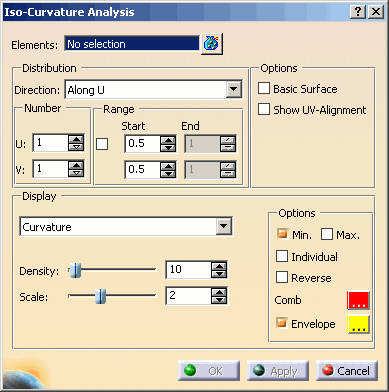
You can define the following options:
- Elements: Elements used for the iso-curvature analysis calculation.
- Distribution: Distribution of the iso curves.
- Direction:
- Along U: All iso curves are displayed parallel to the U direction of each selected surface element.
- Along V: All iso curves are displayed parallel to the V direction of each selected surface element.
- Along U & V: All iso curves are displayed parallel to both the U and V directions of each selected surface
element.

- Number U or V: Number of iso-curvature lines to be displayed in the direction for both U and V directions.

Hint: If only one iso curve per direction is displayed, you can use the point manipulator to move the iso curve.
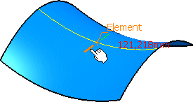
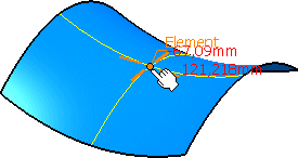
- Range: The number of iso curves displayed is within the range specified.
- Start U or V: The iso-parametric position of the 1st iso curve in the direction for both U and V can be specified.
- End U or V: If the number of iso curves entered is greater than 1, a parameter range can be specified
in which the curves will be displayed. The number of curves are equally spaced between the parameter start and end
values.
Direction: Along U
Range Start: 0.5
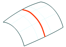
Direction: Along V
Range Start: 0.5
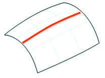
Direction: Along U & V
Range Start: 0.5
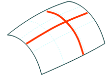
Direction: Along V, Number U: 6
Range Start: 0.3, End 0.8
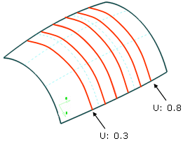
- Options:
- Basic Surface: Computes the analysis on the basic surface in case of faces.
- Show UV Alignment: If an Iso-curvature analysis is computed on multiple surfaces which have a non-uniform parameter flow, the result along the U or V direction will not be displayed in the same direction. The UV direction of each feature has to be aligned to adjust the direction of the analysis results. If the check button Show UV Alignment is switched on, a manipulator will be shown for each surface of the selected features. These manipulators indicate the current UV alignment as well as the surface normal. The UV direction can be inverted via a manipulator point at the normal vector.
- Display: Parameters controlling the display of the spikes depending upon the 'Scale' value.
- Curvature: The spikes normal to each analysis curve will display the curvatures (1/r). The longer the spike length the smaller the curvature will be.
- Radius: The spikes normal to each analysis curve will display the curvature radii (r). The longer the spike
length the larger the curvature will be.
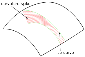
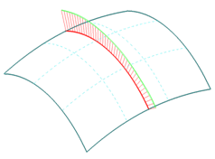
- Density: Discretization grid of equally distributed curvature spikes as they are displayed across the total
length of the iso curve.
Density = 10
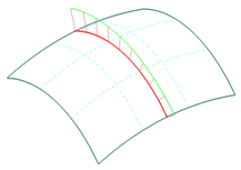
Density = 40
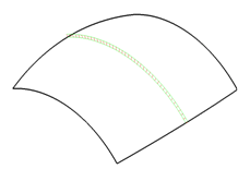
- Scale: Display scale factor for the curvature spikes.
Scale = 50
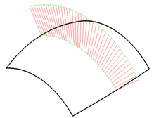
Scale = 3
- Options
- Min/Max: Displays local minimum and local maximum radii values of the computed iso curves.
- Individual: If this check button is switched on, the minimum and maximum radius value of the computed iso-lines will be displayed in the graphics for each individual surface.
- Reverse: Inverts the normal direction of the curvature spikes.
- Comb: Selection of a color for the iso-curvature lines and comb for either U or V direction.
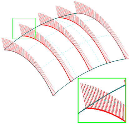
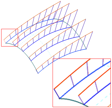
- Envelope: Selection of a color for the envelope that encompasses the iso-curvature comb in either U or V
direction. This envelope can be turned on or off.
Manipulators and contextual commands
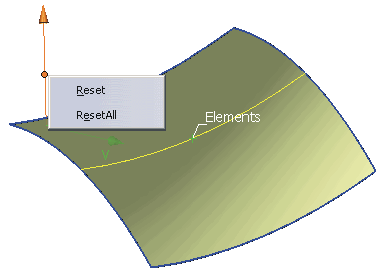
Manipulators are displayed for every surface of the selected features if the check button Show UV Alignment is switched on. The UV direction can be inverted via a manipulator point at the normal vector. A contextual command can be activated with the right mouse button providing options for partially or completely restoring the original geometry:
- Reset: Reset of a single edge.
- Reset all: Complete reset of the original geometry. All modifications will be undone.
![]()