This task explains how to create a NURBS blend curve between two given curves.
Open the BlendCurves.CATPart document.
-
Click the Blend Curves icon
 .
.
The 'Blend Curve' dialog box opens.
-
Select the two curves at one end.
-
Press 'Apply' to display the blend curve.
-
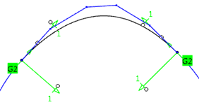
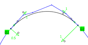
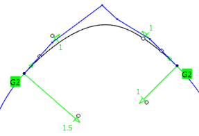
Set the continuity to G2.
-
Move the handle at the end of the manipulator to vary the radius of the blend curve.
-
Click 'OK' to create the blend curve.
- Curve 1/2: Selection of the two curve end points can be carried out between which the blend curve is to be generated.
 Trim: The original
curves will be trimmed at the end points of the connecting curve.
Trim: The original
curves will be trimmed at the end points of the connecting curve.- Surface 1/2 : Selection of surfaces to which the blend curve shall be connected.
Start and end point of the blend curve can be controlled via limit manipulators, direction and transition conditions will be adopted from the corresponding surface.
Tension manipulators are providing an additional angle handle. A contextual command can be activated with the right mouse button where the direction at start and end of the blend curve can be defined. - Support: This option is only available, if the option 'Curve 2' is activated.
The check button activates the selection of a support surface.
As the use of a support leads to some restrictions in the creation of a blend curve, the result can only be influenced with the options 'Adapt' and 'Continuity: G0-G3'.
The values of the tension manipulators act in U/V space.

Note: Depending on the parametrization of the support surface, the default tension values might not lead to good results.  Adapt: This option is only
available, if the check button 'Support' is switched on.
Adapt: This option is only
available, if the check button 'Support' is switched on.
If Adapt is switched on, the blend curve will be created with the same parametrization as the specified support surface.
Blend Curve on a Support WITHOUT Adapt
Blend Curve on a Support WITH Adapt
Which parameter is taken from the support surface for the adaptation depends on the blend curve direction. For example, if the tangents from the input curves (with a certain tolerance) point into U direction of the support surface, the U parametrization. If they point in V direction, the V parametrization is taken (see figure below).
Parametrization used for the adaptation

- Curve 1 options, Curve 2 options
- Continuity: The continuity conditions can be defined before creating the blend curve. Default setting is
G1.
 Link: The continuity conditions of both curves
can be linked.
Link: The continuity conditions of both curves
can be linked.
- Start Radius: Definition of a radius at the appropriate curve end. This option can only be activated for
continuity G2. If a radius is specified, the manipulator at the appropriate curve end is no longer available.
Depending on the users choice of options, the segmentation of the result curve will change:
no radius value set > 1-segment curve
1 radius value set > 2-segment curve
2 radius values set > 3-segment curve
Definition of radius values at both curve ends
- Invert: Inverts the radius by using the negative value.
- Mid Continuity: Continuity condition for the middle part of the connecting curve when a radius is defined.
This option is only available if 'Start Radius' is switched on.Mid Continuity = G1 Mid Continuity = G2 
- Link: The continuity conditions of both curves
can be linked.
- Direction: The tangent and curvature continuity can be adopted from any other curve. The position is adopted from the adjacent curve in either case. In the case of a matching between Curve 1 and Curve 2 where a clear direction is not determined, you can define a direction via this selection field or the contextual menu.
- Limit: A new start point can be defined by selecting a point or curve.
- Continuity: The continuity conditions can be defined before creating the blend curve. Default setting is
G1.
- Display: Depending on the options selected, values are displayed in the graphics area.
- Dynamic, Static, None: See Apply Modes
- Deviation (Side 1/2): Maximum deviation of the blend curve at its start and end position.
- Check buttons: The maximum deviation can be displayed in the graphics for each side.
- G1 - G3: Display of the maximum deviation between 2D curve and support.
Note: In the 'Deviation' field values are only output if the check button 'Support' is switched on.