 |
This task explains how to create a styling corner, that is a connecting curve of a given radius between two
planar curves.
|
 |
The purpose of this command it to provide the capability to create a styling corner element which is computed
between two existing curves with the specified Radius.
|
 |
Open the StylingCorners.CATPart document.
|
 |
-
Click the Styling Corner icon
 . .
The Styling Corner dialog box opens.
|
|
| |
-
Select the curves in the quadrant where the styling corner shall be created.
-
Select the Curve Type Arc.
|
 |
| |
-
Enter a Radius of 50 mm and click Apply. The styling corner is displayed.
You can modify the radius either by entering another value in the Radius dialog or using the manipulators in the graphic area.
|
 |
| |
-
Activate the Curve Type Shape Blend and the option Center
Radius. Enter a center radius of 20 mm.
-
Click Apply to create the styling corner with an lead-in arc and the center radius specified.
In the graphics area, an additional manipulator is available to modify the shape.
|
 |
 |
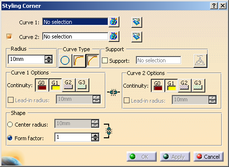
You can define the following options:
- Curve 1, Curve 2: Select the curves between which the styling corner shall be created.
If the check button for Curve 2 is switched off, you can also select a single curve for the styling corner creation.
If several solutions are possible, the computed solution depends on the selection points on the curves or the selection point
on the single curve.
The styling corner is created in the quadrant with the smallest parameter distance of the styling corner end points to the
selection points.
 Trim
Curve 1/2: The input curves can be trimmed at the corresponding end point of the created styling corner. Trim
Curve 1/2: The input curves can be trimmed at the corresponding end point of the created styling corner.
The original input curve is placed in no-show mode.- Radius: Defines the lead-in points of the styling corner into the input curves by specifying
an arc radius value.
|
| |
- Curve Type: Defines the fillet type.
 Arc:
The styling corner is an arc with a defined Radius, the arc radius. Arc:
The styling corner is an arc with a defined Radius, the arc radius.
The arc radius determines the position of the lead-in points of the styling corner.
If the curve tangent vectors of the input curves at the ends of the arc are located in the same plane, tangent continuous
transitions are realized.
  Blend: Calculates the styling corner from the radius and the continuity specified.
 Shape Blend: Calculates the styling corner from the radius and the continuity specified.
With all continuities higher than G0, the shape can additionally be influenced with
Center radius and Form factor.
- Support: The styling corner can be projected onto a surface or plane.
- Support: If the check box is selected, a surface or plane to be used as projection base can be selected.
 Projection: Projects
the styling corner in normal direction onto the selected support. Projection: Projects
the styling corner in normal direction onto the selected support.
|
| |
- Curve 1/2 options: These options are only available for the curve types Blend and
Shape Blend.
- Continuity:
 : Creates the styling corner with position
(G0) continuous transition to the input curve. : Creates the styling corner with position
(G0) continuous transition to the input curve. : Creates the styling corner with a lead-in arc with
tangent (G1) continuous transition to the input curve. : Creates the styling corner with a lead-in arc with
tangent (G1) continuous transition to the input curve.
The lead-in points are defined by the Radius.
In case of using Curve Type Shape Blend, the styling corner can be modified via
Center radius and Form factor. The transition quality will be
preserved after the modification. : Creates the styling corner with a lead-in arc with
curvature (G2) continuous transition to the input curve. : Creates the styling corner with a lead-in arc with
curvature (G2) continuous transition to the input curve.
The lead-in points are defined by the Radius.
You can specify a Lead-in Radius at the lead-in points. However, in this case the transition quality will
NOT be preserved.
If curve type Shape Blend is selected, the styling corner can be modified via
Center radius and Form factor. The transition quality is preserved
after the modification. : Creates the styling corner with torsion
(G3) continuous transition to the input curve. : Creates the styling corner with torsion
(G3) continuous transition to the input curve.
Curvature and torsion radius at the lead-in points are adopted from the input curve.
- Lead-in radius: This option is only available for G2.
Definition of a lead-in radius at the lead-in points with a lead-in arc with G2 continuous transition to the input curves.
The G2 continuity will NOT be preserved.
|
 |
| |
- Shape: This option is only available for curve type Shape Blend.
Defines the fillet shape:
- Center radius: Specifies the radius in the middle of the styling corner in case
of a lead-in arc with G1, G2, or G3 transition to the input curves at the lead-in points.
The continuity will be preserved.
- Form Factor: If lead-in arcs have been created using G1, G2,
or G3 transition, the tangent length of the styling corners is modified. Values smaller than 1 create flat
fillets, values higher than 1 steep fillet.
The continuity will be preserved.
|
|

|