Creating Associative Dimensions
|
|
This task shows you how to create associative dimensions on a 2D drawing generated from a 3D document. | |
|
|
Associative dimensions are created by using the 3D points on the connectors of HVAC parts. The 3D points are added by using a validation check in the Design Validation tool. | |
Add 3D Points |
||
|
|
1. | Open the 3D document from which you want to generate a drawing. |
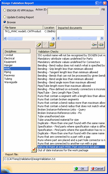
| 2. | Select Analyze > Design Validation Report. | |
| The Design Validation Report dialog box appears. | ||
| 3. | Select your design document and the output file where you want to generate the report. | |
| 4. | In the Disciplines pane, select
HVAC. Scroll down and select Add a 3D Point at each HVAC Part connector
location in the Validation Checks pane.
|
|
| 5. | Click OK. | |
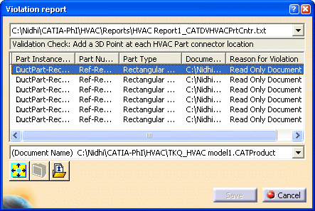
| An error report appears, if there
is an error; otherwise the Validation Summary Report appears showing the
result of the design check. This validation check is unique for HVAC
parts and it may change your design. For more information about design validation, see Using the Design Validation Tool. |
||
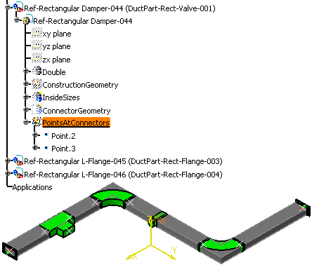
| 3D points are added at each HVAC
part connector. In the specification tree, you can see these points under
the geometrical set Points
AtConnectors. If this geometrical set doesn't exist already, it is
created.
|
||
|
|
Warning:
|
|
Generate a Drawing |
||
| 6. | Click Start > Mechanical Design > Drafting to start a new drawing. | |
|
|
Note: Select Tools > Options > Mechanical Design > Drafting. Ensure that the Project 3D points option on the View tab is selected. | |
| 7. | Click Window > Tile Vertically to view both the 2D and 3D documents. | |
| 8. | Click Front View
|
|
| 9. | Select a plane from the
specification tree in the 3D document and click anywhere in the 2D
document to generate a drawing. For more information, see Generating a
Drawing.
|
|
Create Associative Dimensions |
||
| 10. | With the drawing open, select
Dimensions
|
|
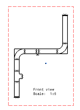
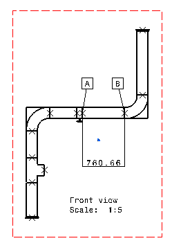
| 11. |
Create a dimension by selecting two 3D points. In the example below, a
dimension of length is created between points A and B (between the
damper and the rectangular elbow).
For more information, see Generative Drafting : Creating Dimensions. |
|
Check for Associativity |
||
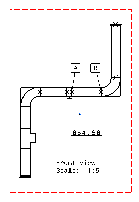
| 12. | In the 3D document, move the damper such that the distance between the damper and the rectangular elbow decreases. | |
| 13. | Update the 2D document, the
distance between points A and B is modified to reflect the
associativity.
|
|
![]()