- Open PanHandle1.CATPart from the
samples directory. It will be the original model.
PanHandle2.CATPart will be used as the comparison model.
Check the Prerequisites
-
Make sure you are starting Compare & Review on CATParts with no review feature.
-
Check that SUN Java plug-in 6 update 10 is available.
-
Check that one of the following browsers is available:
- Under Windows: IE6, IE7 and Firefox 3.0,
- Under Unix: Firefox 3.0
-
To generate the HTML report, use the Environment Editor to set the following environment variables(compulsory). See Customizing Your Environment on Windows in the Installation & Deployment User's Guide.
- CATReport={path of CATReport directory}
- CATTemp={ path of CATTemp directory}
- CATInstallPath={ path of intel_a directory}
- JavaROOT_PATH={directory path of java virtual machine}

This directory must include a sub directory "bin", where the java.exe file is stored. In Internet Explorer, select Allow Block Content in order to run java scripts.
-
By default, the File Selection dialog box lets you open files on disks.
To open documents already loaded in your session:- Go to Tools > Options > General > Document > Document Environments.
- Set Loaded document to Allowed.
Compare
-
Open the first (Old) CATPart (PanHandle1.CATPart from the samples directory).
-
Click Compare & Review
 .
. -
In the File Selection dialog box that appears, select the second (New) CATPart (PanHandle2.CATPart from the samples directory).
The Compare Parts dialog box is displayed.
-
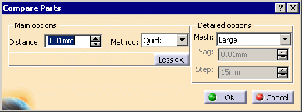
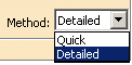
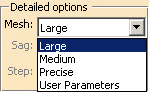
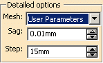
Set the parameters. Those parameters are modal.
-
Click OK.
Progress bars are displayed and the comparison can be interrupted.
The command computes a list of areas seen from the Old model and a list of areas seen from the New model.
In general, a modification is made on an area from the Old model and an area from the New model. In some cases, a modification contains only one area, e.g. when a hole has been created in the New model.A new CATPart MergeResult is created.
Review
List the Modifications
-
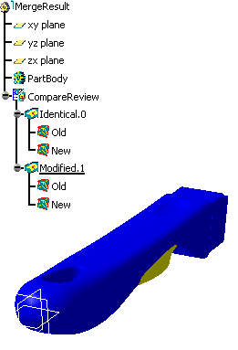
Go to the CATPart MergeResult.
Identical areas are blue, removed (Old) geometry is red and added (New) geometry is green. -
Double-click the feature CompareReview in the specification tree.
The Compare for Review dialog box is displayed:
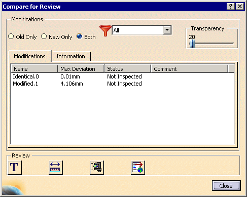
-
- Old Only: shows only removed areas (red),
- New Only: shows only added areas (green),
- Both: shows removed and added areas.
-
Filter the modifications:
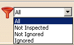
This filter does not impact the final HTML report. -
Transparency helps the visual comprehension. Use the slider to tune the transparency level.
Note that Transparency is applied to identical geometry only. -
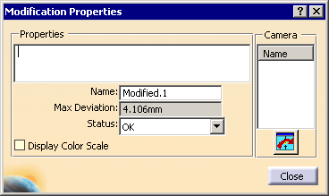
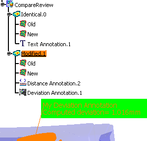
In the list of modification, you find:
- The identical areas. This item is the first which appears in the HTML report.
- The name of the modifications. The default name is Modified.xx. This name is editable.
- The value of the maximum deviation.
This value is always greater than or equal to the distance comparison.
The unit is the unit of the session.
For identical areas, this value is lower or equal to the distance comparison. - The status of the modification:
- Not inspected (default value): means that you have not given a status for this modification.
- OK or KO: means you have
analyzed the modification.
The modification will appear in the HTML report. - Ignored: means you have analyzed the
modification and found it to be non significant.
This modification will not appear in the HTML report. - Adding information, e.g. a comment, a camera or an annotation, on a modification does not change its status.
- The
comment associated to the modification.
The comment is editable.
It appears in the HTML report.
-
Inspect the modifications:
- Select a modification in the list or in the
specification tree, this modification is highlighted.
The modification is displayed with its triangles.
The review annotations of this modification are displayed.
The default camera of this modification is activated. - If you create review annotations, they will be aggregated to the current activated modification.
- Preselection does not modify the dialog box.
- If a modification if filtered out, it is not displayed in the list.
- Select a modification in the list or in the
specification tree, this modification is highlighted.
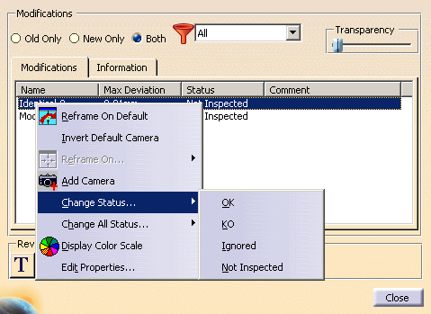
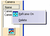
Use the Contextual Menu
-
Right-click the list to start the contextual menu and change the status of one or all items.

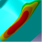
Use the Color Scale
-
Either right-click a modification in the Compare for Review dialog box and select Display Color Scale, or double-click a modification in the specification tree and select the Display Color Scale check box in the Modification Properties dialog box.
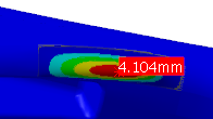
- In the 3D viewer, the current modification is displayed with a color map.
- The location and value of the maximum distance on
the current modification appears as a red label.
- The Color Scale dialog box opens.
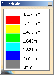
- Lower variations are blue while higher variations are red.
- Note that the color scale depends on the modification and
its maximum deviation.
As a consequence, two modifications with different maximum deviations will have different scales.
Either select Display Color Scale in the contextual menu again or clear the Display Color Scale check box to revert to the standard color display.
Check the Information
-
Go to the Information tab to check:
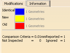
- The color of the identical, added (New) and removed
(Old) areas.
Double-click the colored square to modify the color. - The tolerance of the comparison.
- The number of areas (added, removed, identical).
- The distance threshold for comparison and the number of Reported, Ignored and Not inspected modifications.
- The color of the identical, added (New) and removed
(Old) areas.
Create Annotations
-
Click
 to add an annotation.
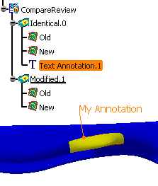
- Select Identical.0: the annotation will be created under this node.
- As you pass the cursor over the model, a cross appears.
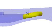
- Pick to position the annotation. A green patch appears.
- Drag it to where you want to position the label and
click.
- A dialog box appears.
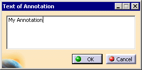
- Click OK. The annotation is created.
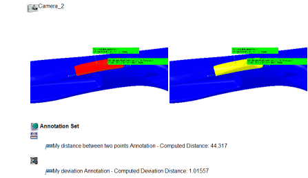
Create Distance Annotations
-
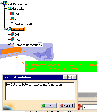
Create a distance between two points annotation:
- Select Modified.1. The distance between two points annotation will be created under this node.
- Click
 .
. - Pick a first point. A green label Computed distance=0 appears.
- Pick a second point. The distance between the two points
is computed and the label is updated.
- Drag the label where you want to position it and click.
- The Text of Annotation dialog box appears.
Enter your comment and click OK.
The annotation is created.
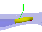
Create Deviation Annotations
-
Create a deviation annotation:
- Select Modified.1. The distance between two points annotation will be created under this node.
- Click
 .
. - As you pass the cursor over the model, a green label is displayed with the deviation found.
- Pick the point where you want to compute the deviation.
- Drag the label where you want to position it and click.
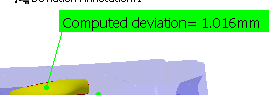
- The Text of Annotation dialog box appears.
Enter your comment and click OK.
The annotation is created.
- To delete a review annotation, right-click it in specification tree and select Delete in the contextual menu.
- To change a graphic attribute on a review annotation, right-click it in specification tree and select Properties in the contextual menu.
- To modify a review annotation, double-click it in the specification tree. You can change the user text and its position.
Generate the report
-
- If all the modifications have not been inspected, the html report may not be accurate.
- Click
 .
The HTML report is generated in the CATReport directory
and opens automatically.
.
The HTML report is generated in the CATReport directory
and opens automatically.
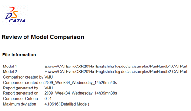
In the HTML report, you will find:
- A main section including general information
generated by the system :
- Name of the review.
- Date of creation the review.
- Date of creation the report.
- User name of the last reviewer.
- Comparison method (Quick or Detailed) and parameters.
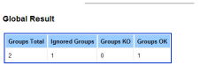
- Number of OK and KO area groups.
- Number of Ignored area groups.
- Maximum deviation.
- The list of OK (in green), KO (in red) and
Ignored groups (in orange):
- For each OK, KO or Ignored area groups:
- The name of group,
- The comment of the group,
- The maximum deviation of group,
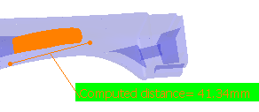
- The list of cameras with 2 snapshots of
the comparison with local annotations.
- One with Old geometry.
- Another with New geometry.
- Note that in this display mode, the transparency is not applied.
Each camera is applied on both models
There is always at least one camera, the default camera. - The list of local annotations with their text.
- For each OK, KO or Ignored area groups:
Note that, when used, the color map is displayed in the report, but not the color scale dialog box.
It looks like this:

Changes regarding visibility (show/no show) impact the model objects and therefore images of report. Any element in no show will be not visible in all images where it is present.
Issue with positioning of graphical representations of Surface Connection Checker
![]()