Defining Continuity to be kept at Opposite End Points or Edges

You can specify continuity constraints at source curve end points or surface edges.

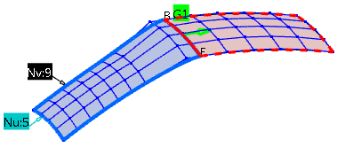
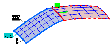
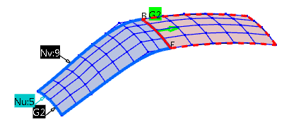
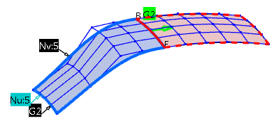
Open a 3D shape containing two surfaces with high orders.
 

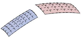
Create a Matching Constraint with Free Continuity at the Source Opposite Edge

  1. Click Matching Constraint in the FreeStyle Constraints toolbar.

  2. In the Source and Target boxes, select the required elements.

  3. Select G1 under Exact  continuity and deselect the Diffusion option.
    In the Tools Dashboard toolbar, select Furtive Display to display the control point mesh during the Matching Constraint command execution.

  4. Click Apply.
    The source is connected with G1 continuity to the target. Only two control point rows are moved.
  5. Undo the last step.
  6. Select the Diffusion option.
    The Source Opposite options are enabled. In the work area, a continuity label appears on the opposite source edge.
  7. Right-click the label and select Free continuity (F).
  8. Click Apply.
    All control points including the opposite edge are moved.
Create a Matching Constraint with Specified Continuity at the Source Opposite Edge
  1. Undo the last step.

  2. Select G1 under Exact  and and G2 Source Opposite continuity.

  3. Click Apply.
    The source is connected G2 continuous to the target and the G2 continuity is kept at the opposite edge.

  4. Undo the last step.

  5. Change the source order in v-direction to five and click Apply.
    The source is connected G2 continuous to the target. At the opposite edge, only G1 continuity is kept, as with the current order, no higher continuity is possible (the continuity with the target has priority over the continuity set at the opposite edge).

    The actually applied continuity is displayed in the dialog box in the Source Opposite area under Applied. In the context menu of the continuity label, the applied continuity is marked with two asterisks.