This task shows you how to change the visualization mode, the element shrink, and the color of a rule based surface mesh part.
- The Rule Based Meshing (RBM) product must be installed.
- A rule based surface mesh part must exist, and you must enter the Rule Based Surface Mesher editor. See Using the Rule Based Surface Mesher Editor.
Change the Visualization Mode
-
Click Mesh Visualization
 .
.The Mesh Visualization dialog box appears. The default mesh visualization mode is the standard visualization.
-
To switch to the quality visualization mode, click Quality Visualization
 .
.Elements with a good mesh quality are colored in green. Elements with a poor mesh quality are colored in yellow. Elements with a bad mesh quality are colored in red. -
To switch to the orientation visualization mode, click Orientation Visualization
 .
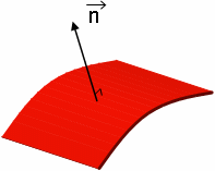
.The mesh elements are assigned blue and red colors. The red color indicates the positive orientation (normal direction):

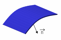
The blue color indicates the negative orientation (inverse of normal direction):

-
Click OK.
 Shrink Element Visualization
-
Click Mesh Visualization
 .
.The Mesh Visualization dialog box appears.
-
Set the shrink coefficients for 2D elements using the corresponding slider.
The shrink coefficient can vary from 1.00 (default value) to 0.50 (minimum value). The element visualization is shrunk dynamically. -
Click OK.
 Color Mesh
-
Click Mesh Visualization
 .
.The Mesh Visualization dialog box appears.
-
In the Mesh type list, select the type of mesh you want to color.
-
To assign a unique color to all meshes that have the same type, select Fixed color, and select the desired color.
-
To randomly assign colors to meshes that have the same type, select Variable color, and enter a value to specify the number of colors you want to use.
-
Click OK.