This task shows you how to remesh one or several domains with a mesh method different from the one defined in the mesh rule file used to create the rule based surface mesh part.
- The Rule Based Meshing (RBM) product must be installed.
- A rule based surface mesh part must exist, and you must enter the Rule Based Surface Mesher editor. See Using the Rule Based Surface Mesher Editor.
-
To remesh domains with the frontal quadrangle method, select Frontal Quadrangle Method
 .
.The Frontal Quadrangle Method dialog box appears. -
Select the domains to remesh in sequence.
-
Enter a value of mesh size.
-
Click OK.
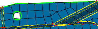
Example of a domain remeshed with the frontal quadrangle method:
-
-
To remesh domains with the frontal triangle method, select Frontal Triangle Method
 .
.The Frontal Triangle Method dialog box appears. -
Select the domains to remesh in sequence.
-
Enter a value of mesh size.
-
Click OK.
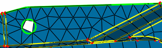
Example of a domain remeshed with the frontal triangle method:
-
-
To remesh a domain with the mapped method, select Mapped Method
 .
.The mapped method generates a mesh as regular as possible using quadrangle elements only. The Mapped Method dialog box appears. -
Select the domain to remesh.
You can select domains with a rectangular, cylinder, or ring topology. - For domains with a rectangular topology, the C0, C1,
C2, and C3 symbols appear on the selected domain to
represent the four corners of the domain, even if the
selected domain has more than four corners. The four corners
are automatically positioned but you can change their
position to enhance the mesh quality.
To change the position of a corner, select the corner you want to change and then, select a vertex. - For domains with a cylinder or ring topology, corners are imposed and not displayed; you cannot modify them.
- For domains with a rectangular topology, the C0, C1,
C2, and C3 symbols appear on the selected domain to
represent the four corners of the domain, even if the
selected domain has more than four corners. The four corners
are automatically positioned but you can change their
position to enhance the mesh quality.
-
Enter a value of mesh size.
-
To split quadrangle elements to generate triangle elements, select the Split quadrangles check box.
-
Click OK.
-
-
To remesh a domain with the mapped free method, select Mapped Free Method
 .
.The mapped free method generates a mesh as regular as possible using both quadrangle and triangle elements. The Mapped Free Method dialog box appears. -
If you want to remesh a domain with a triangular topology, select the 3-side domain check box.
-
Select the domain to remesh.
You can select domains with a rectangular, triangular, cylinder, or ring topology. - For domains with a rectangular or triangular topology,
symbols appear on the selected domain to
represent the corners of the domain (C0, C1, C2,
and C3 for rectangular domains; C0, C1, and C2
for triangular domains). The corners
are automatically positioned but you can change their
position to enhance the mesh quality.
To change the position of a corner, select the corner you want to change and then, select a vertex. - For domains with a cylinder or ring topology, corners are imposed and not displayed; you cannot modify them.
- For domains with a rectangular or triangular topology,
symbols appear on the selected domain to
represent the corners of the domain (C0, C1, C2,
and C3 for rectangular domains; C0, C1, and C2
for triangular domains). The corners
are automatically positioned but you can change their
position to enhance the mesh quality.
-
Enter a value of mesh size.
-
Click OK.
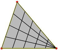
Example of a triangular domain remeshed with the mapped free method:
-
-
To remesh domains with the minimal method, select Minimal Method
 .
.The minimal mesh method uses the existing nodes and topology constraints, and no internal nodes are created. The Minimal Method dialog box appears. -
If you want to remesh a domain with a triangular topology, select the 3-side domain check box.
-
Select the domain to remesh.
-
Click OK.
-
-
To remesh a domain with the bead method, select Bead Method
 .
.The Bead Method dialog box appears. -
Select the domain to remesh.
At least two vertices are needed. The C0 and C1 symbols appear on the selected domain: 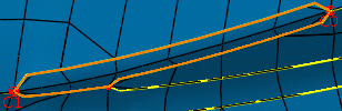
To change the position of a corner, select the corner you want to change and then, select a vertex.
-
Enter a value of mesh size.
-
Click OK.
-
-
To remesh a domain with the half bead method, select Half Bead Method
 .
.The Half Bead Method dialog box appears. -
Select the domain to remesh.
At least three vertices are needed. The C0, C1, and C2 symbols appear on the selected domain. To change the position of a corner, select the corner you want to change and then, select a vertex. -
Enter a value of mesh size.
-
Click OK.
-
-
If a remesh specification is already defined on the selected domain, a warning message appears. Click one of the following:
- Yes to replace the existing remesh specification by the current one.
- No to keep the previous remesh specification.