This task shows you how to impose nodes when you modify a rule based surface mesh part. You can impose nodes by distributing them on a particular edge, around a particular hole, or by propagating an existing node distribution.
- The Rule Based Meshing (RBM) product must be installed.
- A rule based surface mesh part must exist, and you must enter the Rule Based Surface Mesher editor. See Using the Rule Based Surface Mesher Editor.
Distribute Nodes on an Edge
You can impose nodes by distributing them on an edge.
-
In the Mesh Edition toolbar, click Edge Distribution
 .
.The Edge Distribution dialog box appears.
-
Select the edge on which you want to impose nodes.
-
In the Type list, select one of the following distribution methods:
- Uniform to distribute nodes on the selected edge with a same distance between nodes.
- Arithmetic to distribute nodes on the selected edge with a distance between nodes defined by a common difference computed with parameters.
- Geometric to distribute nodes on the selected edge with a distance between nodes defined by a common ratio computed with parameters.
- User law to distribute nodes on the selected edge with a distance between nodes defined by a knowledge law previously defined in the Knowledge Advisor workbench.
-
For Uniform, Arithmetic, and Geometric distributions, select the parameters you want to use to define the distribution in the Defined by list.
The list and number of parameters to define varies depending on the distribution method. - For Uniform distributions, only one parameter
among the following list is needed:
- Number of edges to impose a specific number of elements edges along the selected edge.
- Size to impose a mesh size on the selected edge.
- For Arithmetic, and Geometric
distributions, two parameters among the four following
parameters are required:
- Number of edges to impose a specific number of elements edges along the selected edge.
- Size ratio to impose a ratio between the size of the last and first edges in the distribution.
- Size at node 1 to impose the size of the first edge in the distribution.
- Size at node 2 to impose the size of the last edge in the distribution.
- For User law distribution, the following
parameters must be defined:
- Number of edges to impose a specific number of elements edges along the selected edge.
- Law to select the desired knowledge law.
- For Uniform distributions, only one parameter
among the following list is needed:
-
If you selected Arithmetic or Geometric, you can choose to distribute nodes symmetrically by selecting the Symmetric check box.
-
If you selected User law, you can reverse the direction of the distribution by selecting the Reverse direction check box.
-
Click OK.
 Distribute Nodes around a Hole
You can impose nodes by distributing them around a hole.
-
In the Mesh Edition toolbar, click Mesh around Hole
 .
.The Mesh around Hole dialog box appears.
-
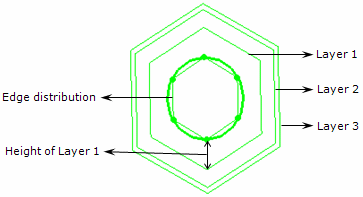
Select the edge that is the contour of the hole.
-
In the Number of edges box, enter the number of edges you want to create around the selected holes.
-
In the Propagate on list, select the number of layers you want to create around the selected hole: One layer, Two layers, or Three layers.
-
For each layer, enter a value to define the height of the layer.
-
Click OK.
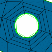
Example of hole remeshed with an edge distribution equal to 6 and three layers:
 Propagate an Existing Node
Distribution
You can impose nodes by propagating an existing node distribution.
-
In the Mesh Edition toolbar, click Distribution Propagation
 .
.The Distribution Propagation dialog box appears.
-
In the Supports box, select the edges on which you want to propagate the node distribution.
Multi-selection of edges is available except for non-manifold configurations (for example, multi-selection is not available for a T-configuration). -
In the Sources list, select the edges that have the distribution you want to propagate.
Multi-selection is available for connected and manifold configurations. -
In the Mode list, select one of the following methods of distribution propagation:
- Proportional to keep the relative distance
between nodes.
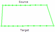
- Projection to keep the direction of the
source/target vector normal to the target support.
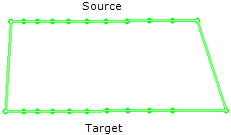
- Directional to keep the direction of the
source/vector parallel to a given direction.
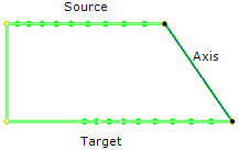
- Proportional to keep the relative distance
between nodes.
-
If you selected Directional, select an axis to specify the direction of the propagation.
-
Click OK.