|
You can remove and fill
features like holes, pockets, or other openings using the
Functional Import Wizard.
The wizard associates the functional behavior of protected, added, and
removed features to these openings. This allows you to use the input
part smoothly with the Functional Molded Part workbench. |

|
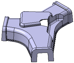
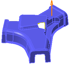
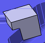
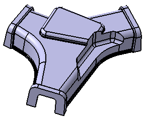
Open the input part that is essentially a thin
part, consisting of a distinct parting element. This parting element
divides the part into an inner surface (core), an outer surface
(cavity), and the parting element itself.
The input part with opening
 |
|
|
|
Define Faces
|
|
|
In the face selection step, you can define the faces required to compute
the openings within the part. |

|
-
Click the Functional Import Wizard
 in the
Basic Features toolbar (Functional sets sub-toolbar) . in the
Basic Features toolbar (Functional sets sub-toolbar) .
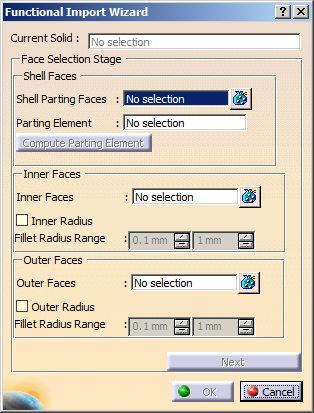
The Functional Import Wizard dialog box is displayed.
-
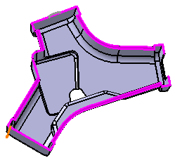
In the Shell Faces area:
- Select the required shell parting faces.
The selected faces are displayed in the Shell Parting
Faces box.
Shell faces are in contact with the parting element. They
divide the part into inner and outer faces respectively.
- The selected faces are highlighted in pink.
- The Compute Parting Element
option is now available for selection.
|
- Select the parting element, if known. You can also
select the Compute Parting Element option, to
select the parting element automatically.
A parting element is the one that supports the shell faces.
The parting element is selected. An arrow defining the area
to be kept is displayed.
|
-
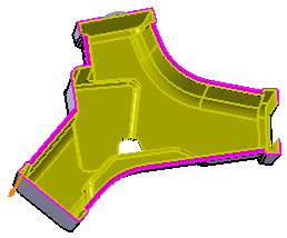
In the Inner Faces area:
- Select the inner faces.
The selected faces are shown in the Inner Faces box.
The selection is done by tangent propagation.
Note: Select all the faces limiting the inner region of the part
except the holes, pockets, or other openings which need to be
filled.
The selected faces are highlighted in yellow.
- To select fillets with certain range of radius, select the
Inner Radius option and define the range of
Fillet Radius Range.
This is needed when the selection extends along a filleted face
of an opening. This helps to stop the tangent propagation from
the face to the opening.
|
-
In the Outer Faces area:
- Select the outer faces.
The selected faces are shown in the Outer Faces
box.
The selection is done by tangent propagation.
Note: Select all the faces limiting the outer region of the
part except the holes, pockets, or other openings which need
to be filled.
The selected faces are highlighted in blue.
- To select fillets with certain range of radius, select
the Outer Radius option and define the range of
Fillet Radius Range.
This is needed when the selection extends along a filleted
face of an opening. This helps to stop the tangent
propagation from the face to the opening.
|
-
Click the Next button to navigate to the
Openings removal step.
|
|
|
Compute and Fill the Openings
|
|
|
Select a type of fill strategy for the opening that is
highlighted in the work area.
The fill strategy decides how exact the fill should be. There are three
types of fill strategies available:
- Minimal Fill: the most exact
fill. The hole is filled with maximum precision. This fill
is attributed with a default minimum offset value of 0.1mm.
- Optimized Rough Fill: the
compromise between the minimal and rough fill. Its exactness
varies according to the opening. The fill is optimal on the
inner side and rough on the outer side.
- Rough Fill: the least exact
fill. The approximation of the opening is very large.
|
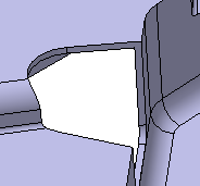
Opening in the input part
 |
Minimally filled
opening
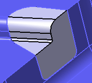 |
Optimally filled opening
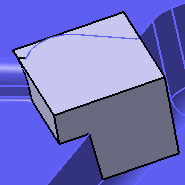 |
Roughly filled
opening
 |
Select the required Feature Type to fill the
opening.
The feature types available are:
Select Compute to compute the highlighted
opening.
Navigate between the openings computed within the part
using << and >>.
Optional: Select Compute All
to apply the current setting of fill strategy and fill feature to all
the openings computed in the part.
Check the Diagnostic Information: section for
the status of the computation.
 |
If the Diagnostic
Information section indicates that
the computation failed, you can change the fill strategy and try
again. |
Click Next button to navigate to
Featurization Step.
|
|
|
Generate Features
|
|
|
Select any of the following options to generate the new
features:
- Thin Solid: to generate a new thin solid.
- Functional Features: to select an existing
solid functional set from the specification tree in the
Select "Solid Functional Set" box.
|
Click Generate.
Based on your selection, the feature is generated.
|