You can, for instance, create capture for:
- Functional part area
- Specifications answering to given functional requirements
- 2D view equivalent
- 2D sheet equivalent
- etc.
the capture creation command ends. However, you can edit the capture using the contextual commands. In this scenario, Edit filter at the end of capture creation command check box is cleared.
-
Select Insert > Capture > Capture
 .
.The Capture Creation dialog box appears. 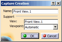

The followings rules are applied during the capture creation:
- A capture is always associated with a
view/annotation plane:
- When the representation does not contain any view/annotation plane, a projection view/annotation plane is created parallel to the xy plane and passing through the origin of the representation.
- When the representation contains at least one view/annotation plane, the active view/annotation plane is selected. However, you can select another view/annotation plane by selecting the View box and selecting a view/annotation plane from the specification tree or from the geometry.
- By default, the capture name is the same as the associated view/annotation plane.
- By default, the view/annotation plane viewpoint
is used.
However, you can select an existing camera from the Viewpoint list. - Cameras are created/managed using the View > Named Views command.
- During the capture creation, the type of Render Style, Parallel or Perspective, is not recorded, neither in the capture feature nor through the associated camera.
- A capture is always associated with a
view/annotation plane:
-
Click OK in the Capture Creation dialog box.
The Front View.1 is created and displayed in the specification tree. -
Right-click the capture in the specification tree and select Properties > Visualization tab and perform the following steps.
- Select the Display in 3D option.
- Type in the Hidden Text field the following text: This is the capture hidden text
- Click OK in the Properties
dialog box.
The name of the capture and a rectangle framing the middle characters of this name appear in the graphic area, and they form the capture callout. When you rotate the part, the capture callout remains parallel to the screen.
The hidden text is displayed when passing over the capture feature.
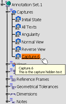
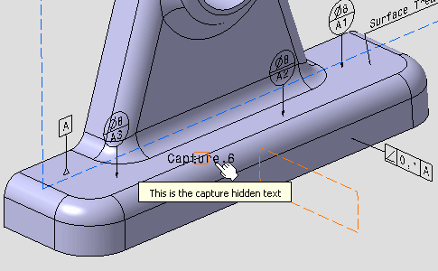
- The text of a capture callout is not editable, but follows the modifications of the capture name.
- The capture properties enable you to customize the display of the capture callout.
- The Position And
Orientation toolbar applies to capture callouts:
- for capture callouts with an associated camera:
- The X,Y manipulation applies to the text of the callout,
- The Z manipulation applies to the text and the pyramid of the capture callout.
- for capture callouts with no associated camera:
- The X,Y manipulation applies to the text and the frame of the callout,
- The Z manipulation is not relevant.
- for capture callouts with an associated camera:
- The capture callout is not linked to any annotation plane.
- The capture callout orientation is fully controlled by the 3D point of view attached to the capture.
- If you change a camera associated to a capture callout, the previous capture callout is deleted and a new one is created.
- If you remove a camera associated to a capture, the capture callout remains unchanged, the information No camera is displayed in the camera list.
-
Move and rotate the part like this.
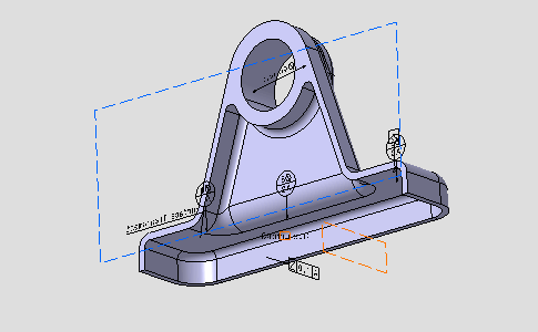
-
Select View >
 Named Views... menu.
 -
Click Add in the Named Views dialog box which appears.
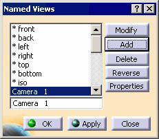
- The Camera 1 is created.
- The part location and zoom are recorded in the camera properties.
- Click the Properties button in the Named Views dialog box to edit these
properties.
As the 3D shape orientation and zoom are recorded in the capture properties, this information is kept even when the associated camera is deleted.
-
Right-click the capture and select Change Capture Support.
The Change Capture Support dialog box appears.
-
Select Camera 1 from the Viewpoint list and click OK.
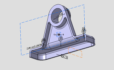
- Camera 1 is now associated with Capture.6.
- The flat rectangle framing the name of the capture is
replaced by a rectangular-based pyramid that represents the
3D view point, see:
- When the capture is activated, the apex is displayed at the center of the screen and the base of the pyramid is parallel to the screen.
- The name of the capture can be moved and a leader can be added.
-
Click Exit from Capture
 .
.
You are back in the Functional Tolerancing and Annotations workbench. 
To edit a capture, double-click the capture in the specification tree, or the 3D when it is displayed. 
We enter the Filter workshop, for editing the capture. When exiting Capture Edition, all the modifications (Show/NoShow status of the annotations, active view, camera, clipping plane, etc.) are kept i.e. visual status of the CATPart is the same as capture edition.
To get back to the previous state, you should create a specific capture before and recall it just after exiting the capture workshop.
3D Preview of capture
When a capture is selected in 3D or in the feature tree, the clipping and section profile of the active view in the capture are displayed.
|
|
The clipping plane and section profile of the
active view inside a capture are displayed only if the 3D-Annotation-Query Switch On/Switch Off
|
You can see that the section profile is displayed as thick orange line and the clipped surface is seen as the green section.
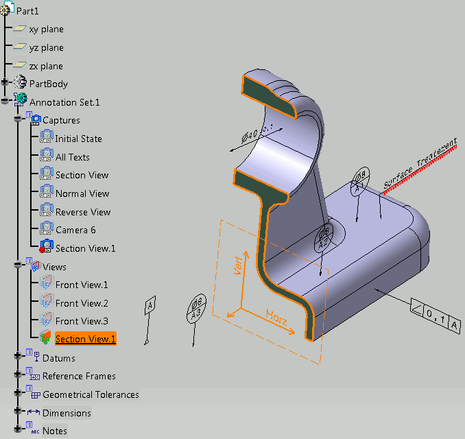 |
-
The clipping plane, which is visualized, helps in better visualization when the active view in a capture is clipped.
-
Section profile is displayed as thick line. The section profile is shown only when the active view of the selected capture is a section cut or a section view. For other views only the clipping will be seen not the profile.
-
The clipped part, which is seen, is similar to when the Clipping Plane
 option is activated. The properties for the representation of
the clipping plane is taken from Tools > Options >
Mechanical Design > Functional Tolerancing & Annotation, Display
tab, Hatching, coloring or dotting for clipping plane
area, Display option
set for the clipping plane.
 -
The status of Clipping Plane command does not impact the capture selection process. Even if the command is deactivated the clipping profile is seen and the view is clipped on capture selection.
-
If Clipping Plane command is activated, the clipping of the active view is displayed. If a capture is selected whose active view is different from the active view in the CATPart, then the clipping of the active view is replaced by the clipping of the active view in the capture. The clipping of the active view will be restored when no capture is selected.
-
If more than one capture is selected, then the last selected capture is taken into account and the profile and clipping plane of its active view is displayed.
-
The Show/No Show status of the capture does not change the behavior. Even if the capture is in No Show mode, the clipping plane and the section profile are still displayed.