-
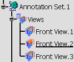
Activate the Front View.2 annotation plane.
-
Click Coordinate Dimensions
 in Annotations
toolbar.
The Tools Palette is displaying allowing you to select the creation of 2D or 3D coordinate dimensions.
-
2D Coordinates lets you create 2D (x, y) coordinate dimensions in the active view axis system.
-
3D Coordinates lets you create 3D (x, y, z) coordinate dimensions in the part/product axis system.
For the purpose of this scenario, make sure 3D Coordinates is selected.
Or right-click anywhere to display the contextual menu.

-
-
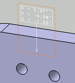
Select a point as shown below.
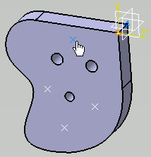
The dimension is created. 
You can select the following elements: a vertex, a point (on a curve, on a plane, a coordinate), a line center or a point on a curve. -
Drag the dimension to position it as wanted.
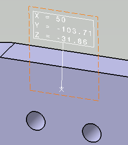
- Once a coordinate dimension has been created, you cannot change its type (i.e. you cannot turn a 2D coordinate dimension into a 3D coordinate dimension, and vice-versa).
Modifying Coordinate Dimension Value Display Format
-
To modify the coordinate dimension value display format, right click the coordinate dimension to display the contextual menu and select Properties (or use Edit > Properties command).
The Properties dialog box is displayed.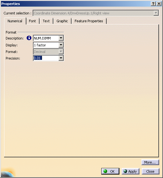
-
Select the Numerical tab. The display format can be changed in the Numerical tab.
Format: You can define and customize the display format for coordinate dimensions.-
Description: Select a type of format. To get a detailed description about the format selected from the drop-down list, click the information point
 icon.
icon.
If the selected format is NUM.DIMM, then the description would be as: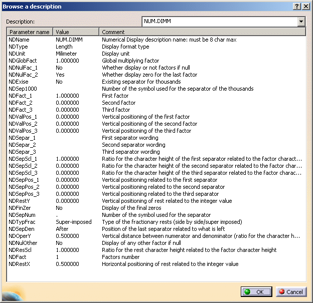

The Description standard and its format values can be customized by the administrator in value formats (Tools > Standards > [standard name] > Value Formats).
-
Display: Depending on selected format, you can choose to display one, two or three factors to be seen.
-
Format: Only decimal format is available.
-
Precision: Select the value precision.

- The properties of the display value format can be customized by the administrator in value display format (Tools > Standards > Drafting > [standard name] > Styles > Coordinate Dimension > Value Display Format). For more information refer to Dimension Styles in Interactive Drafting User Guide.
- If new styles have been defined by the administrator in Tools > Standards for this type of element, these will be displayed in the Style toolbar drop-down list. The properties of the element can then be changed by selecting another style from the list.
-
-
Select description as FEET-INC and Display factor as 2.
-
Click OK. The coordinate dimension display value is changed.
If only the description format name and precision value is to be changed, then you can use Numerical Properties toolbar and select the values from the drop-down list.
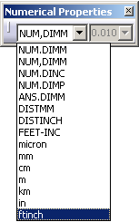

- Each coordinate dimensions can have different display parameters (format description, precision value, etc.).
- The Display Units option (via Edit > Properties, Text tab) is available for only those pre-R18 coordinate dimensions that do not have format information.
- When the given format name is not valid (corresponds to an existing value format description or left blank), the coordinate dimension on which the style is applied or the NUM.DIMM format, or the first allowed in the AllowedNumericalFormats will be applied.
- For pre-R18 drawing:
- If the option Use style values to create new objects is checked in Tools > Options > Drafting, Administration tab, the description information will not be set and the resulting coordinate dimension will follow the old display.
- If this option is cleared the value available in the Numerical Properties toolbar will be used.