The task deals with creation of basic dimensions using:
- Restricted areas, where basic dimensions define the restricted area dimensions and location.
- Datum targets, where basic dimensions define the datum target location from another datum target or geometrical elements.
- Datum reference frames, where basic dimensions define the datum reference frame location from reference elements or representing constructed geometry.
- Geometrical tolerances (Position, Angularity, Surface profile, Line Profile), where basic dimensions define the toleranced element location from references in the reference frame.
Manual Creation of Basic Dimensions
To improve the highlight of the related geometry, see Highlighting of the Related Geometry for 3D Annotation.
-
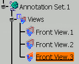
Double-click the Front View.3 to activate it.
-
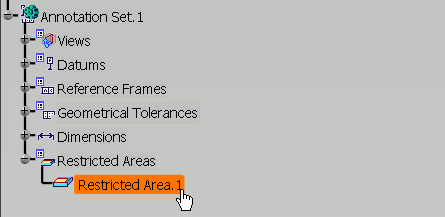
Select the Restricted Area.1 partial area.
The Framed (Basic) Dimensions Management dialog box appears. 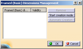
-
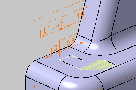
Select dimensions as shown on the part.
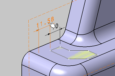
The dimension is converted into a basic dimension when clicking. 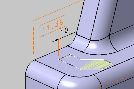
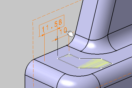
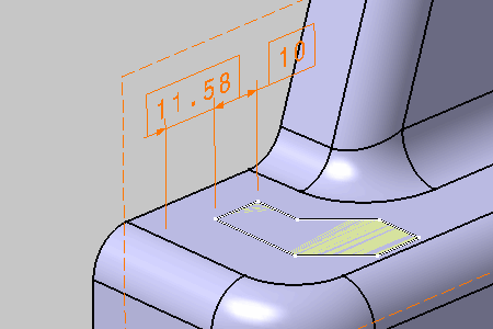
The Framed (Basic) Dimensions Management dialog box is updated. The validity of each converted annotation is checked. 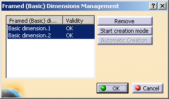
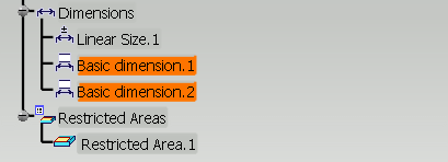 |
-
Click Start creation mode in the Framed (Basic) Dimensions Management dialog box.
-
Select edges as shown on the part.
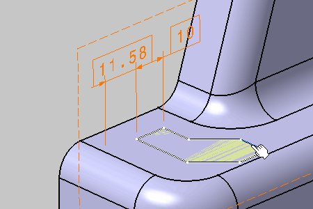
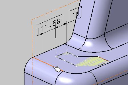
The basic dimension is pre-created. 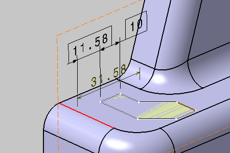
-
Click in the free space to create the basic dimension.
-
Click End creation mode in the Framed (Basic) Dimensions Management dialog box.
-
Select Basic Dimension.1 in the Framed (Basic) Dimensions Management dialog box, and click Remove.
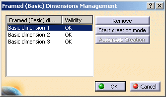
The basic dimension has been removed. 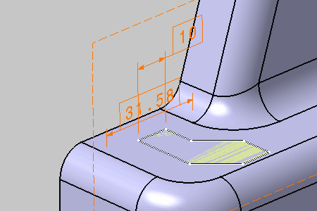
-
Click OK in the Framed (Basic) Dimensions Management dialog box.
Automatic Creation of Basic Dimensions
- Improve the highlight of the related geometry, see Highlighting of the Related Geometry for 3D Annotation.
- Position tolerances have been created for the patterns.
-
Click Framed (Basic) Dimensions
 in
Annotations
toolbar.
 -
Select the position tolerance.
In this case select the position tolerance of circular pattern.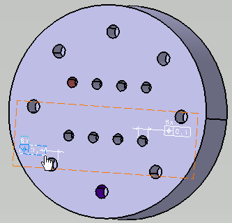
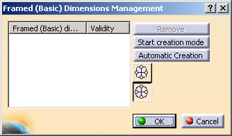
The Framed (Basic) Dimensions Management dialog box appears. There are two types of Automatic Creation modes: - Rectangular Coordinates
 : The related
positioning of the pattern components will be
defined by rectangular coordinates
 - Cylindrical Coordinates
 : The related
positioning of the pattern components will be
defined by cylindrical coordinates.
By default the cylindrical coordinates mode is selected.
- Rectangular Coordinates
-
Click Automatic Creation button in the Framed (Basic) Dimensions Management dialog box with the cylindrical coordinates
 mode.
mode.
The basic dimensions are automatically created for the circular pattern. The information is updated in the Framed (Basic) Dimensions Management dialog box.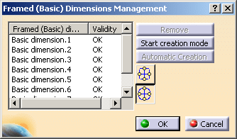
-
Click OK in the Framed (Basic) Dimensions Management dialog box.
You can see that the basic dimensions are created for the circular pattern.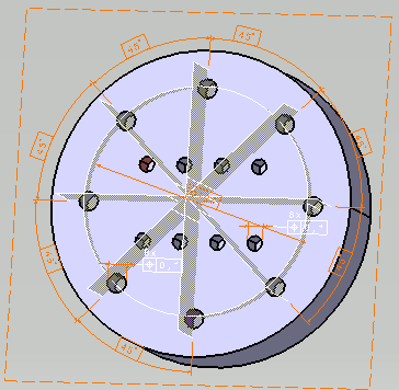
-
If the Rectangular Coordinates
 mode is
selected, the information is updated in the Framed
(Basic) Dimensions Management dialog box.
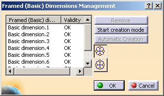
The basic dimensions are created for the circular pattern with rectangular coordinates.
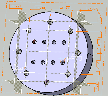
-
Click Framed (Basic) Dimensions
 in
Annotations
toolbar.
 -
Select the position tolerance.
In this case select the position tolerance of rectangular pattern as shown.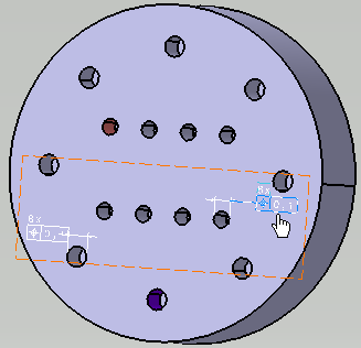
The Framed (Basic) Dimensions Management dialog box appears. - Click
Automatic Creation in the
Framed
(Basic) Dimensions Management dialog box.
The basic dimensions are automatically created for the rectangular pattern. The information is updated in the Framed (Basic) Dimensions Management dialog box. 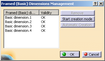
- Click
OK
in the Framed
(Basic) Dimensions Management
dialog box.
You can see that the basic dimensions have been created for the rectangular pattern.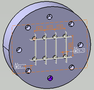
More about Basic Dimensions
- The framed dimensions created will be attached in priority to the active view. If the active view is not suitable for a given framed dimension, it will be attached to the first suitable view from the list of already created views and if none is suitable, a new suitable view is automatically created.
- The framed dimensions that belong to the same view are as far as possible are aligned together. The framed dimensions that have the same dimension line orientation will be placed at the position along the normal of the dimension line orientation
- You can use undo command to remove the currently created basic dimensions. The construction geometry, the framed dimensions and the views created using the Framed (Basic) Dimensions command are removed.
- If the basic dimensions and construction geometry already exist, they will not be created twice.
- In case of automatic creation, localization geometrical tolerance without datum reference frame can be applied to a circular or rectangular pattern of constructed geometries for thread.