See 3D Annotations and Annotation Planes concept.
- Improve the highlight of the related geometry, see Highlighting of the Related Geometry for 3D Annotation.
-
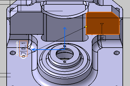
Right-click the annotation as shown on the part and select the Associated Geometry > Geometry Connection Management from the contextual menu.
The Connection Management dialog box appears.
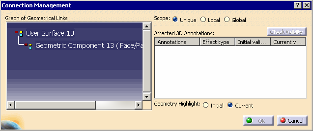

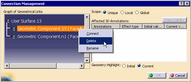
In Graph of Geometrical Links, the feature linked to the selected annotation is displayed. If the linked feature is in Hide state, the last child feature in the specification tree in Show state and of the highest priority level is displayed. -
Check that Unique option is activated in Scope.
-
Right-click User Surface.13 in the Graph of Geometrical Links as shown and select the Add Geometry from the contextual menu.
You can also select Add multiple Geometries to add several geomtries at a time.
A new geometric component is added to the user surface User Surface.13 feature and prompt you to select the new geometrical element to be linked to the annotations.
-
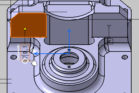
Select the surface as shown on the part.
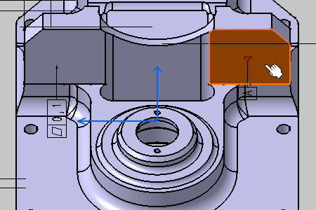
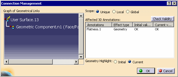
The Connection Management dialog box displays the new added geometry to the structure: Geometric Component.n1 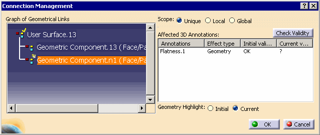
-
Click the Check Validity command to check the new geometry component validity relative to the selected annotation.
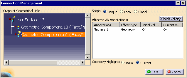
-
Click OK.
The two geometric components are now link to the annotation. 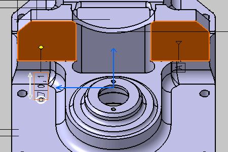
-
Right-click the annotation again and select the Geometry Connection Management contextual menu.
