Before you begin you should be familiar with the following basic concepts:
What Type of Analysis for What Type of Design?
You will find here below three methodological cases for generating mesh, depending on the type of the geometry.
![]() GPS: Generative Part Structural Analysis workbench
GPS: Generative Part Structural Analysis workbench
![]() FMS/FMD: Advanced Meshing Tools workbench
FMS/FMD: Advanced Meshing Tools workbench
![]() GSD: Generative Shape Design workbench
GSD: Generative Shape Design workbench
![]() PRT: Part Design workbench
PRT: Part Design workbench
Analyzing in Generative Part Structural Analysis Workbench (GPS) After
Meshing in Advanced Meshing Tools workbench (FMS/FMD)


The selected FMS mesh part will be used for analysis.
This mesh contains triangle and quadrangle shell elements. Those elements can be linear (three nodes - four nodes) or parabolic (six nodes - eight nodes). They have six degrees of freedom per node (three translations and three rotations) to take into account membrane and bending effects.
The thickness of the part needs to be specified by double-clicking on Material Property in the specification tree.
All the preprocessing specifications (Loads, Restraints, Masses) will have to be applied to the geometries that were selected in FMS workbench.
Analyzing in Generative Part Structural Analysis (GPS) Workbench
Surface Geometry Designed in Generative Shape Design (GSD) Workbench

- First case
You first indicated in GSD which geometry you want to be analyzed by going into Tools > External View commands from the menu bar.
The following will be generated: mesh parts and shell properties.
A 2D Octree mesh Part is automatically created when starting GPS.
This mesh part will generate triangle shell elements. Those elements can be linear (three nodes) or parabolic (six nodes). They have six degrees of freedom per node (three translations and three rotations) to take into account membrane and bending effects.
- Second case
You did not indicate in GSD which geometry you want to be analyzed.
You will have to use Mesh Part commands to generate Mesh Parts and properties commands to generate properties.
Notes
- You can edit, delete or re-create mesh parts and properties at any time. In case of inconsistencies, use the Check command
.
- All the specifications (Loads, Restraints, Masses) will have to be applied to a geometry on which a mesh part and property have been created.
Analyzing in Generative Part Design (GPS) Workbench Solid Geometry
Designed in Part Design (PRT)

- A 3D OCTREE mesh Part is automatically created.
- This mesh part will generate tetrahedron elements. Those elements can be linear (four nodes) or parabolic (ten nodes). They have three degrees of freedom per node (three translation).
- All the preprocessing specifications (Loads, Restraints, Masses) will be applied to the Part Body geometry.
What Type of Hypotheses are Used for Analysis?
You will find here below three types of hypotheses used when working in Analysis workbench.
- Small displacement (translation and rotation)
- Small strain
- Linear constitutive law: linear elasticity
For static case solutions, one can say that:
- If there is no contact feature (either virtual or real), no pressure fitting property and no bolt tightening (either virtual or real) feature, then the problem is linear, that is to say, the displacement is a linear function of the load.
- If there is at least one contact feature (being virtual or not) or pressure fitting property or bolt tightening (being virtual or not) feature, then the problem is non linear, that is to say, the displacement is a non linear function of the load.
About Supports
Analysis specifications can be applied to different types of supports (or features):
- Geometrical Feature
- Point/Vertex (except GSM points)
- Curve/Edge
- Surface/Face
- Volume/Part
- Groups (points, curves, surfaces, parts)
- Mechanical Feature
- Analysis Feature
To learn more about supports you can select when you define an analysis specifications, see Authorized Supports the Frequently Asked Questions section.
When you select a mechanical feature, the analysis specification is actually applied on the resulting associated geometry. If this geometry is not an authorized geometrical supports (refer to the corresponding table in the Authorized Supports chapter), you will not be able to select the mechanical feature. For example, selecting a fillet for a Line Force Density will not be allowed because the resulting geometry of a fillet are surfaces while the authorized geometrical entities for Line Force Density are lines or edges.
Analysis specifications cannot be applied to elements used to build geometries (such as points to build a line, sketch to build a filled surface,...). To apply analysis specifications to geometries built using other elements, we recommend to first hide those elements. For example: to apply a restraint to an extremity of a beam, you need to first hide the point that has been used to create the line that represents the beam, and then select the extremity of the line (and not the hidden point because this point is not linked to the mesh).
Simplified mesh
When you apply an analysis specification to a geometry,
the analysis specification is applied to the mesh that is associated with the geometry.
Depending on the Details simplification options you set when
you mesh a geometry (the Others tab of the Octree 2D or 3D
dialog box), the mesh associated with the selected geometry can be
simplified (for example, removal of small edges when you select the
Mesh edge suppression check box is selected). The analysis
specification is then applied to a simplified mesh that does not
correspond to the initial geometry when small geometries are ignored.
In this case, a warning message is displayed after launching a
computation using the Compute capability (whatever the option
you selected) to warn you that the analysis specification is applied to a
simplified mesh, and that this configuration can lead to unexpected
results.
If this message appears, you can change the Details simplification options in the Others tab of the Octree 2D or 3D dialog box, you can also refine the mesh or change the support.
Consider a clamp specification applied to an edge as follow:
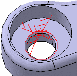
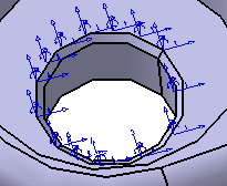
When the Mesh edge suppression check box is cleared, the mesh is not simplified, and the clamp is applied to all the nodes of the selected edge as shown by the following Degrees of freedom image:
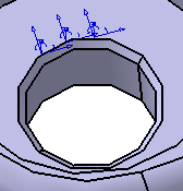
When the Mesh edge suppression check box is selected, the mesh is simplified and, the clamp is partially applied to the selected edge as shown by the following Degrees of freedom image:
CATAnalysis Document Size
A .CATAnalysis document is created when you enter the Generative Structural Analysis workbench. You can save on disk a CATanalysis file even if its size is upper than 2Gb.
For the size of the CATAnalysisComputations and CATAnalysisResults files (files generated when you launch a computation), refer to Specifying External Storage.
Launching the Solver
The below capability is only available with the ELFINI Structural Analysis (EST) product.
The kernels steps of the solver are launched transparently on a different process.
This concerns the steps that are consuming a lot of memory. The slave process will benefit from small contiguous available memory for computation.
It is strongly recommended that you extend the memory of the used machine with extended paginated memory. The master process will automatically paginate its own data on this paging memory.
Improving Performance on Multi-processor Computers
Windows
The ElfiniSolver is multithreaded if more than one processor is found.
You can specify the number of processors to be used with the OMP_NUM_THREADS environment variable.
AIX
By default, all the available processors are used.
You can specify the number of processors
to be used with the UNIX command:
export XLSMPOPTS="parthds=2" (if you want to use two
processors)
Loading / Unloading Documents
In the analysis context, we recommend to deactivate the
Work with the cache system option located in the
Infrastructure > Product Structure > Cache Management tab
(Tools > Options menu).
You can unload geometry document (CATPart, CATProduct)
using the File > Desk menu.
Unloading a document allows you to liberate memory while working on large
models (post-processing and computation). Moreover, specifications you have
defined are kept up-to-date.
In the FileDesk workbench, right-click the CATPart or CATProduct document you want to unload and select the Unload contextual menu:
In this example, the pointed documents (two CATPart files) are also unloaded.
For more details, refer to Using the FileDesk Workbench in the Infrastructure User's Guide.
Miscellaneous
DMU Space Analysis workbench:
Any CATAnalysis document that will be imported into a product needs to be updated if you wish to use it in DMU Space Analysis workbench.