-
Click Auto Update Flatten Link
 in the Update
Flatten Links
toolbar.
in the Update
Flatten Links
toolbar. -
In the flattened harness document, select a bundle segment.
The bundle segment is identified in the geometry area. -
In the 3D harness document, select a bundle segment.
The bundle segment is likewise identified in the geometry area. -
Click in the geometry area to start the comparison.
The algorithm used is that set in the Flattening Harness Parameters. The entire harness is browsed automatically starting from the bundle segment selected first. The algorithm compares components two-by-two to see if they are identical, and if conditions are met, then maps the two components.
If several solutions are possible, the algorithm informs you and waits for user input.You can select a bundle segment to be mapped in the flatten data by clicking on the displayed labels:
- Within the flatten data editor, following
labels are displayed:
- The red label indicating the name of the flatten bundle segment to map.
- The green labels indicating the
name of possible bundle segments available
in the 3D harness design data
which could be mapped with the selected flatten bundle segment. - The green NONE label
to be used for the case where the selection
is not possible among the suggested
bundle segments, or if no mapping is needed.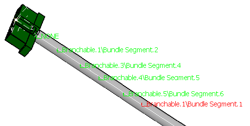
- Within the 3D harness design data editor, in parallel, the green labels indicating the name of the corresponding bundle segments to be mapped are displayed.
If you click on a label within the flatten data editor, it will switch to the advanced mode. The object name
displayed in the label within both flatten data editor and the 3D harness design data editor will be expanded to
show more precise information.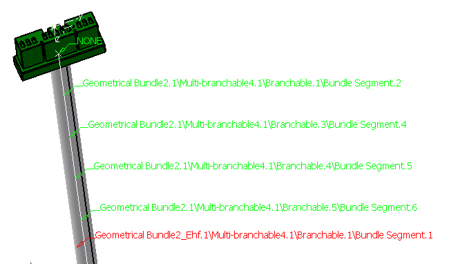
If you click on the label again within the flatten data editor, it will switch back to the normal mode
(default label display). Note that while clicking the label in the flatten data editor, the corresponding segment in
the 3D harness data editor will also be highlighted along with the path change of the label.When the comparison is complete, components whose flatten links have been properly updated are highlighted in both documents.
The mapped components are highlighted in both documents at the end of the command.
Press Esc or select the components to make them no more highlighted. - Within the flatten data editor, following
labels are displayed:
Mapping by Topological Algorithm
Mapping conditions are different for each harness component and take into account tolerance values specified.
- Bundle segments: must be of the same length and diameter.
- Devices: must have the same Reference Designator or instance name.
- Internal splices: must belong the same mapped bundle segment and have the same abscissa along the electrical curve.
- Supports: must belong to the same mapped bundle segment and have the same abscissa along the electrical curve.
- Protective coverings: must belong to the same mapped and covered bundle segment and have the same abscissa along the electrical curve.
- Wires and wire groups: must have the same From/to end and be routed along the same route.
Mapping by Naming Algorithm
Mapping conditions are based on the naming of the Reference Designator if valuated. If this attribute is not valuated, then mapping is based on the Instance Name.
If attributes have the same name, then components are mapped successfully.
Special case for supports: since supports are not considered electrical components, they do not have Reference Designator attributes. The user can, however, specify a user-defined attribute, naming it Reference Designator.