") |
Open the
Excavation01.CATPart
model the from the samples directory.
It includes:
- Dam, representing the dam you want to build across the valley, and
its axis (DamAxis)
- LandSurface, representing the top soil layer,
- RockLayer, representing the rock layer underneath the
LandSurface,
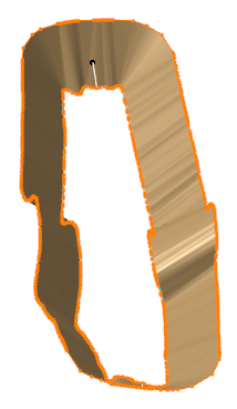
- MeshIntersection, that is the scan resulting from the intersection of
the RockLayer and the Dam.
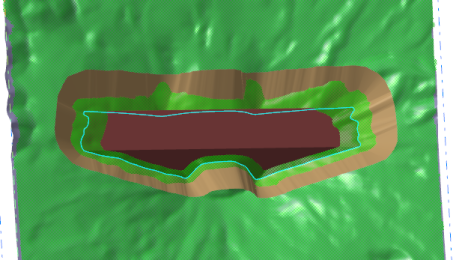
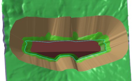
The excavation surface lets you compute the volume of soil to dig
out, delimited by the excavation surface, the LandSurface and
the RockLayer. |
 |
-
Click Excavation
 in the Terrain Modeling toolbar.
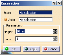
The Excavation dialog box is displayed:
-
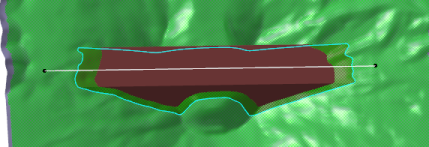
Select the
Scan you want to process.
This scan is the intersection between:
- The mesh representing the building for which you want to compute the
excavation,
- The mesh representing the layer on which the building is
built, here the rock layer.
It is usually a closed scan.
In our example MeshIntersection.1.
 |
-
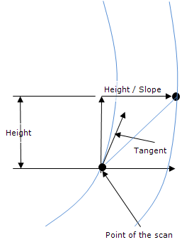
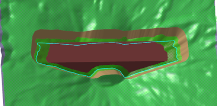
If required, modify the Parameters:
- Height: height of the resulting mesh,
- Slope: slope of the resulting mesh, defined as follows:
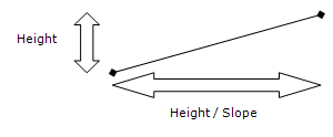
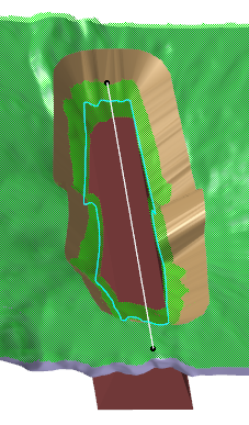
- Height=10, Slope=1:
- Height=20, Slope=1:
- Height=10, Slope=2:
|
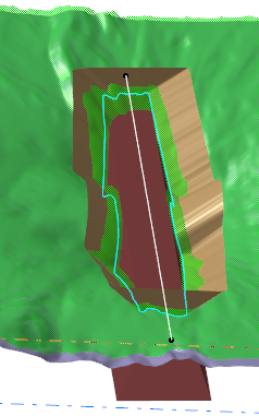
-
According to your needs, select or clear the Axis check box.
By default, it is selected.
|