Section views make drawings more readable by replacing the hidden elements of parts, including holes, with filled areas.
-
In the drawing window, click Offset Section View
") in the Views toolbar (Sections sub-toolbar).
in the Views toolbar (Sections sub-toolbar). -
Select the holes and points to define the cutting profile on the view. SmartPick assists you when creating the profile.
Note that selecting a circular edge, a linear edge, an axis line or a center line (for example, a hole) makes the view callout associative by default to the corresponding 3D feature. If you select a circle, the callout will go through the circle center. If you select an edge, the callout will be parallel to the selected edge.

If you are not satisfied with the profile you create, you can, at any time, use the Undo  or Redo
") icons.
icons.As you select the second point, the section plane appears and moves dynamically on the 3D part while you define the profile on the drawing. This section plane will automatically disappear when you double-click to end the callout definition.
-
Double-click to end the cutting profile creation. A preview is displayed.
-
Define the section view position using the cursor.
")
Positioning the view also defines the section view direction, as if it were a left or a right projection view. The direction of the callout blue arrows changes as you change the cursor position. -
Click to generate the view. A progress bar appears while the view is being created.
Using the cursor, you can then position the section view in order to align it, or to not align it, to the front view.

- The patterns which are used to represent sections are defined in the standards. For more information, refer to Pattern Definition in the Interactive Drafting User's Guide.
- You may modify the pattern (hatching, dotting, coloring or motif). For more information, refer to Modifying a Pattern.
About Creating Section Views on Broken Views
You can create an offset or an aligned section view or a section cut
in a view which already contains a single/multiple broken profiles.
A view having single/multiple broken profile(s) can be divided into
number of zones. For example, consider the following view with two
broken operator profiles:
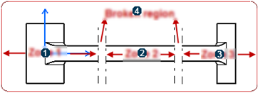
| 1 | Zone 1 |
| 2 | Zone 2 |
| 3 | Zone 3 |
| 4 | Broken region - the area between the broken operator profile lines. |
In this case, you can create valid aligned or offset section profile types such as section callout in single zone, or across broken region but with certain rules as mentioned below:
| Types of Profiles | Description | Section Callout Creation |
Section callout profile in single zone |
All the callout profile segments lie completely in Zone 1, Zone 2 or Zone 3 and do not intersect/cut any broken operator profile lines. | Possible |
Section callout profile partially in broken
region This case is possible only when a section callout profile is already present in the view and then a broken profile is created such that part of the section callout profile is encompassed inside the broken region. |
If some of the profile segments of section callout are present in the broken region and remaining of them are strictly present in a single zone. | Not possible |
Section callout profile across the broken region |
If some of the end segment points of section callout profile are present in Zone 1 and some of the segment end points are present in adjacent Zone 2, crossing the broken region. | Possible when perpendicularity rule is followed. |
Section callout profile completely in the broken
region |
If all the segments of the section callout profile are present completely inside the broken region zone. | Not possible |
Section callout profile across multiple broken
region zones |
If some or all segment end points of section callout profile are present on either side of the multiple broken operators. | Possible when perpendicularity rule is followed. |
Consider the following points when creating an aligned section callout profile:
|
Similarly, consider the following points when creating an offset section callout profile:
|

However, if an invalid profile is created, a message appears informing that such a section callout profile cannot be created.
|
|
You can create a broken profile on a view which already contains a section callout profile without any restrictions. |
Edition of Section Callout Profile
You can edit the section callout profile or create a completely new
section callout profile by right-clicking the callout and selecting
Replace Profile.
You can edit only valid section callout profiles. A warning message
appears when you try to edit an invalid section callout.
After edition of a section callout is complete, the resultant callout has to be a valid one and follow the same rules as mentioned in the above section.
The following table gives the summary of edition of section callout
profiles:
| Section Callout Profile in Single Zone | Section Callout Profile Partially in NML Zone | Section Callout Profile Across the NML Zone | Section Callout Profile Completely in NML Zone | Section Callout Profile across Multiple NML Zones | |
| Section callout profile before edition | YES (Aligned/Offset) | NO | Allowed when perpendicularity rule is followed. (Aligned) | NO (Aligned/Offset) | Allowed when perpendicularity rule is followed. (Aligned) |
| Allowed when perpendicularity rule and even number rules are followed. (Offset) | Allowed when perpendicularity rule and even number rules are followed. (Offset) | ||||
| Section callout profile after edition | VALID (Aligned/Offset) | INVALID | Allowed when perpendicularity rule is followed. (Aligned) | RESTRICTION (Aligned/Offset) | Allowed when perpendicularity rule is followed. (Aligned) |
| Allowed when perpendicularity rule and even number rules are followed. (Offset) | Allowed when perpendicularity rule and even number rules are followed. (Offset) |
Visualization of Section Callout Profiles
You can click the Callouts node in the tree or directly click on the callout profile and visualize the section callout fully or in a truncated manner or not visualize it at all, depending on the type of section callout profile.
The following table summarizes the visualization of section callout
profiles:
| Section Callout Profile in Single Zone | Section Callout Profile Partially in NML Zone | Section Callout Profile Across the NML Zone | Section Callout Profile Completely in NML Zone | Section Callout Profile across Multiple NML Zones | |
| Aligned/Offset Section Callout |
COMPLETELY SEEN | TRUNCATED | COMPLETELY SEEN/TRUNCATED | NOT SEEN | COMPLETELY SEEN/TRUNCATED |
An invalid profile is seen as truncated and it does not follow the Perpendicularity rule or the Even Number rule.
Propagation of Broken and Breakout Specifications
You can propagate the broken and breakout specifications of a view to a newly created view.
To propagate the breakout and broken specifications to a section view, select Propagation of broken and breakout specification check box from Tools > Options > Mechanical Design > Drafting > Layout tab.
For aligned section callout, the broken specifications are propagated
only if it is a valid single segment callout and it crosses all the
broken operators present in that view.
For offset section callout profile, the broken specifications are
propagated only if it is a valid callout profile and it crosses all the
broken operators present in that view, and the first segment of this
valid section callout is perpendicular to the broken operator lines. (It
is valid for a single as well as multiple segment callout).
![]()