Aligning Views Using Elements |
|
-
Right-click the view that you want to re-position and select View Positioning > Align Views Using Elements.
-
On this view, select the first geometrical element that you want to align.
This element may be projected either as a point, a line or a circle (aligned according to its center). A visual feedback is provided to indicate the kind of geometry detected, and in the case of a line, its orientation (the orientation being determined by the proximity of the pointer with one of its extremities).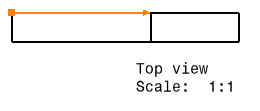
-
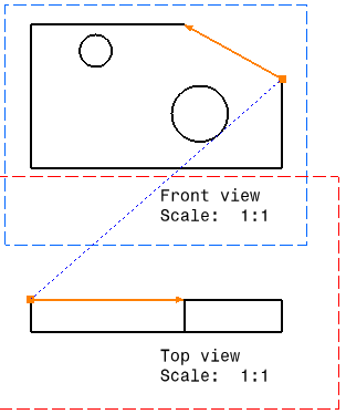
On the reference view, select the second geometrical element that you want to align.

- If both the selections are lines, you can press Shift before clicking the second element to view where both the line origins meet. This gives a visual feedback: a blue dotted line joining the lines origin points. In this case, both the lines are made collinear and their origin points coincident.
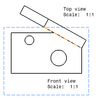
- If the lines are parallel, both the views are aligned.
- If the lines are non-parallel, the first view is oriented according to the reference element selected, without any alignment.
The first view is moved, and both views are aligned according to the elements and orientations you selected. Any associative positional link that existed between the two views prior to their alignment is removed, and no new one is created.

If you want to restore an associative positional link between the views, you can right-click the view and select View Positioning > Position According to Reference View.
When aligning views, remember that if you select a circle as one of the elements to align, this circle will be aligned according to its center.
Superposing Views |
|
-
Right-click the view that you want to superpose, the front view with dress-up, for example. A contextual menu is displayed.
-
Select View Positioning > Superpose.
-
Click the view on which you want to superpose the first view. The first view is moved and superposed to the second one.
-
Click in the drawing, outside the views, to validate the superposition.
Setting Relative View Position |
|
-
Right-click the view frame that you want to re-position, the isometric view for example. A contextual menu is displayed.
-
Select View Positioning > Set Relative Position.
A direction positioning line appears that is related to the isometric view. This isometric view can be positioned as desired and relatively to the front view. Note that the isometric view is assigned anchor points.
-
Select the direction positioning line end black square point.
Once you have clicked the end square point, this point becomes a blinking red end point and remains so until you select a point or a view frame.
You can also click the direction positioning line. In this case, the positioning line becomes a blinking line and remains so until you select a line (callout line).
Press the Ctrl key to move the positioning line according to a direction that is parallel to the positioning line. -
Click the edge according to which you want the isometric view to be aligned.
-
Click one anchor point, for example, the bottom right one. The view anchor point is aligned according to the green point and thereby to the direction positioning line.
-
As you move the cursor over the direction positioning line, the position and length coordinates of the line appear.
Note that you may also select the front view frame and align the isometric view to the front view according to the barycenter. ")
-
Using the green point, you can rotate the isometric view around the front view.
")
-
Using the direction positioning line, translate the isometric view along the direction line and locate it at the desired distance.
")
If you happen to modify the length of the direction positioning line, this new length will be kept whatever positioning modifications you may apply to the isometric view. Note that if you had previously positioned this isometric view according to a point, not only the line length but also the line angle will be kept.
-
Click in the free space to validate and leave the relative positioning mode.
") |
![]()