and generate the required material additions.
-
Click Material Addition Wizard
 in the Plies toolbar.
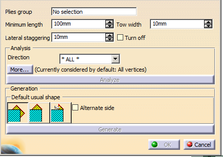
The Material Addition wizard dialog box is displayed.
-
Key in:
-
Optional: Select the Turn off check box to minimize the ply crossing.
- If Turn off
is not selected, the
lateral staggering is
computed.
- If Turn off
is selected, only the
minimum cut length is
taken into account.
- Turning the lateral
staggering off is
different from setting
it to 0.
- If Turn off
is not selected, the
lateral staggering is
computed.
-
Optional: Filter the plies by selecting a Direction from the list.
All the plies with the selected direction are processed. -
Optional: Click More... for more criteria:
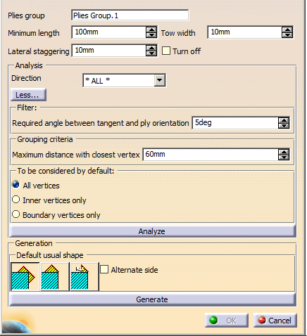
Select one of the Usual Shapes icon to initialize the addition of material:
 :
Adds a rectangular shape to the ply, with a 45/135 degrees
draping angle, a 90 degrees shape angle, and both sides
positioning (rectangle) for all vertices.
:
Adds a rectangular shape to the ply, with a 45/135 degrees
draping angle, a 90 degrees shape angle, and both sides
positioning (rectangle) for all vertices.  :
Adds a triangular shape to the ply, with a 45/135 degrees
draping angle, a 90 degrees shape angle, and one side
positioning (triangle) for all vertices.
:
Adds a triangular shape to the ply, with a 45/135 degrees
draping angle, a 90 degrees shape angle, and one side
positioning (triangle) for all vertices.  :
Adds a triangular shape to the ply, with a
normal return to contour, a 45/135 degrees draping angle, a
shape angle that ensures a normal return, and one side
positioning (triangle) for all vertices. The return angle may be
more than 90 degrees.
:
Adds a triangular shape to the ply, with a
normal return to contour, a 45/135 degrees draping angle, a
shape angle that ensures a normal return, and one side
positioning (triangle) for all vertices. The return angle may be
more than 90 degrees.
-
If a better balance of material addition is required, select Force alternate side.
- If Force
alternate side is
not selected, the
material is added always
on the same side.
- If Force
alternate side is
selected, the material
is added on one side,
then on the other.
- If Force
alternate side is
not selected, the
material is added always
on the same side.
-
Click Analyze.
The wizard: - Finds all the ply contour vertices with discontinuities in tangency,
- Ignores those where the discontinuity is already the result of a material addition,
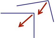
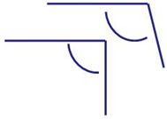
- Checks the angle between the tangents at the vertices
and
ignores the vertices where this angle is too large, e.g.- This angle is valid:
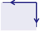
- This angle is invalid:
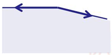
- This angle is valid:
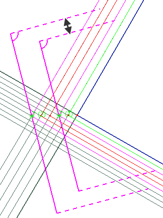
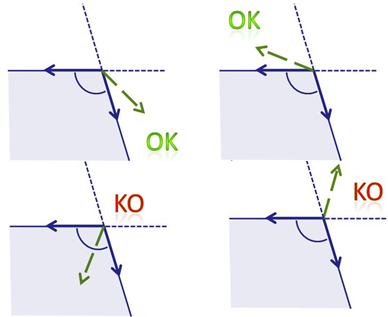
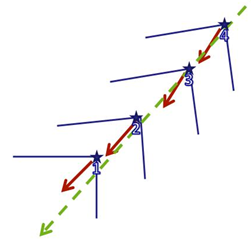
- Checks the angle between each tangent and the ply
orientation (displayed in dash green below)
and ignores the vertices where this angle is lower than Minimum angle ply orientation vs tangent, e.g.- This angle is valid:
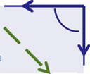
- This angle is invalid:
- This angle is valid:
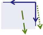
- Finds out whether a material addition is needed or not:
it computes an offset from the vertex, equal to the Tow width,
parallel to the direction of the ply orientation.
A material addition is required if the length of this curve is smaller than the Minimum length.
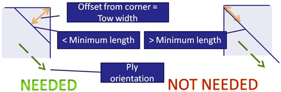
- Ignores vertices where the ply orientation is not
consistent with the tangents.
Then, the wizard groups the vertices
- Having the same ply orientation,
- Complying with the Maximum distance with closest vertex,
- Having almost the same bisector as the first vertex of
the group,
- Having almost the same angle between tangents,
Within a given group, the vertices are ordered according to their abscissa along an average bisector.
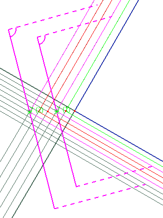
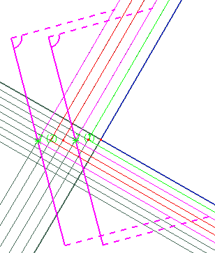
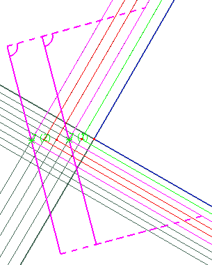
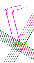
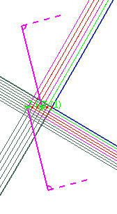
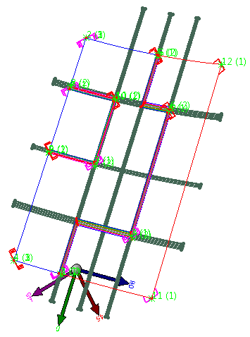
All locations of possible material addition are then previewed in the 3D viewer,
with some (not all) possible modifications, based on the active Default usual shape.
-
For a non-symmetrical usual shape, click the preview to change the side of the material addition
-
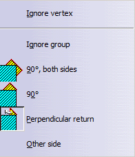
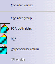
For any Default usual shape, right-click the preview to access its contextual menu:
-
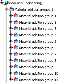
When you have made all required modifications on the previews, click Generate.
The material additions are generated.
-
Click OK in the Material Addition wizard dialog box to validate and exit.
![]()