Adding material to a ply reverts to merging a 4-side polyhedron to the ply contour, e.g.:
 resulting
in
resulting
in
or resulting in
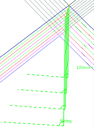
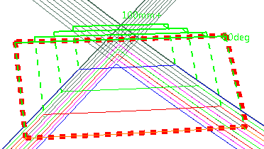
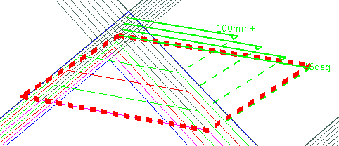
- The red line represents the Minimum length,
- α represents the Shape angle,
- β represents the Fiber draping angle.
- Lateral staggering is shown below:
- The blue line represents the material width, which is not
imposed.
Hence cases like the following one are not supported:
-
Click Material Addition
 in the Plies toolbar.
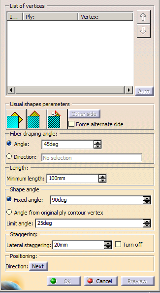
The Material Addition dialog box is displayed:
-
Pick the vertices of the plies to be modified.
The dialog box is updated:
-
Select one of the Usual Shapes icon to initialize the addition of material:
 :
Adds a rectangular shape to the ply, with a 45/135 degrees
draping angle, a 90 degrees shape angle, and both sides
positioning (rectangle) for all vertices.
:
Adds a rectangular shape to the ply, with a 45/135 degrees
draping angle, a 90 degrees shape angle, and both sides
positioning (rectangle) for all vertices.  :
Adds a triangular shape to the ply, with a 45/135 degrees
draping angle, a 90 degrees shape angle, and one side
positioning (triangle) for all vertices.
:
Adds a triangular shape to the ply, with a 45/135 degrees
draping angle, a 90 degrees shape angle, and one side
positioning (triangle) for all vertices.  :
Adds a triangular shape to the ply, with a
normal return to contour, a 45/135 degrees draping angle, a
shape angle that ensures a normal return, and one side
positioning (triangle) for all vertices. The return angle may be
more than 90 degrees.
:
Adds a triangular shape to the ply, with a
normal return to contour, a 45/135 degrees draping angle, a
shape angle that ensures a normal return, and one side
positioning (triangle) for all vertices. The return angle may be
more than 90 degrees.;
-
When adding a triangular shape, click Other side if you need to change the side where the material is added.
-
Click Preview.
The polyhedron is visualized on the last selected ply.
The parameters modification applies to this ply.
You can define different parameters for the plies listed in the dialog box.
Those parameters are editable: The display of the polyhedron is updated in the 3D window as you modify the parameters.
Messages are displayed when the computation of the added material is not possible or requests your attention.
-
If a better balance of material addition is required, select the Force alternate side check box.
- If Force
alternate side is
not selected, the
material is added always
on the same side.
- If Force
alternate side is
selected, the material
is added on one side,
then on the other.

- If Force
alternate side is
not selected, the
material is added always
on the same side.
-
Define the Fiber draping angle:
- Either type the angle value,
- Or select the Direction option and then select a curve.
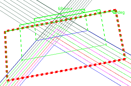
Below the angle has been changed from 45 to 60 degrees:
-
If necessary, modify the Minimum length:
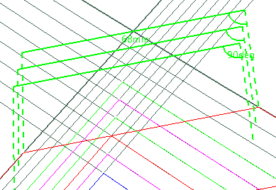
- Minimum length=100:
- Minimum length=200:

- Minimum length=100:
-
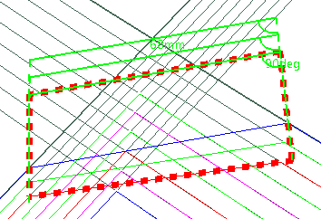
Define the Shape angle.
- Either as a Fixed angle:
- Or as an Angle from original ply contour vertex:
- Either as a Fixed angle:
-
Define the Limit angle, that is the minimum value for the Shape angle.
-
Define the value of the Lateral staggering (represented by the double-headed arrows below).
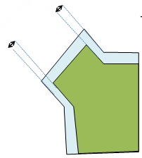
If you need to minimize ply crossing, select Turn off.
- If Turn off
is not selected, the
lateral staggering is
computed.
- If Turn off
is selected, no lateral
staggering is selected,
only the minimum cut
length is taken into
account.
- Be aware that
turning the lateral
staggering off is
different from setting
it to 0.
- If Turn off
is not selected, the
lateral staggering is
computed.
-
Optional: Modify the Positioning:
- Either click one preview line in the 3D window,
- Or click Next in the dialog box.
The material addition preview is positioned at the next possible location.
-
Click OK when you are done.
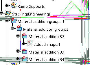
The Material addition is created in the 3D window as well as in the specification tree.
![]()