-
Click Local Drop Off
 in the Grid Design toolbar.
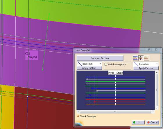
The Local Drop Off dialog box is displayed:
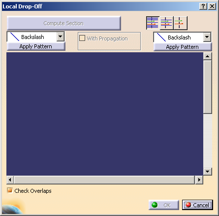
-
Pick a point on a structural element:
A limited intersection of the plane perpendicular to the structural element
and the reference surface is displayed (green line limited by two green handles below):
It defines the section to be considered.
If necessary, drag one of the handles to resize this section. -
Click Compute Section in the dialog box.
The section is computed and displayed in the viewer of the dialog box:
- Standard V5 pan and zoom commands are available in this viewer.
- The ramp support curves available within the section limits are
displayed as vertical dotted lines.
The structural element you have picked is displayed as a white dotted line.
The plies are displayed as horizontal full lines, in different colors:
- A ply selected in the dialog box viewer is highlighted in the specification tree and in the 3D viewer.
- When you place the cursor over a ply, information about this ply is
displayed in the viewer:
- Plies that fully cover the cells on both sides of the section limits
(full plies) are displayed with no handles,
and cannot be moved:

- The plies that do not fully cover the cells on both sides of the
section limits are displayed with handles:
-
Drag an handle to move a ply from one ramp support curve to another.
-
 displays all full plies,
 -
 displays only relevant full plies,
 -
 hides all full plies.
-
-
Select the With Propagation check box.
- When you apply a new pattern, V5 will try to use the
ramps already used by the plies
just before applying this new pattern. - If there is not enough ramps, V5 will then use the curves used to compute the section.
- If these two steps are not successful, you will be asked to use all the curves of the ramp supports.
- When you apply a new pattern, V5 will try to use the
ramps already used by the plies
-
Select the Check Overlaps check box.
The curves are checked for overlaps and the list of the overlaps found is displayed.
If With Propagation is selected, this check applies to all the curves of the ply contours
where the propagation is applied. -
On each side of the section, you can:
- Either apply a drop-off pattern selected in the
list:
- or modify the drop-off manually by moving plies as explained above.
- Either apply a drop-off pattern selected in the
list:
-
Once you are satisfied, click OK to validate and exit the dialog box.
a dialog box is displayed with that information.
Click:
- Yes to move the ply. If an overlap occurs, a warning is displayed.
- No to cancel the move.
- Swap to swap the positions of both plies.
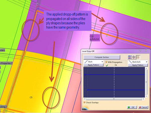
Applying a Pattern on Plies with the Same Shape
-
Open GAAngleCut01.CATPart and compute a section as explained in steps 1 to 3 above.
-
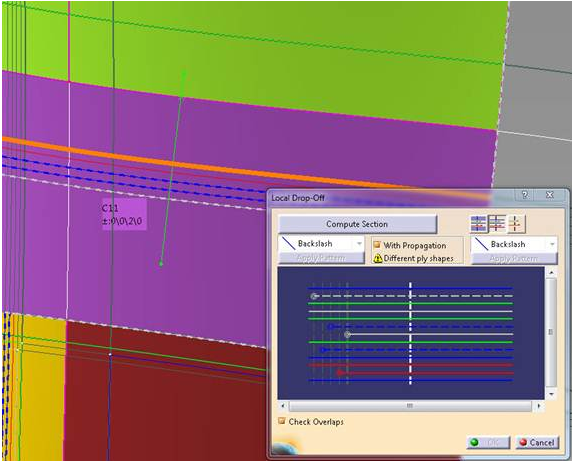
Select the With Propagation check box to find plies with the same shape.
A diagnostic is displayed under With Propagation.
Plies with different shapes are shown as dotted lines.
-
Using the handles, restrict the section definition to the plies with the same shape.
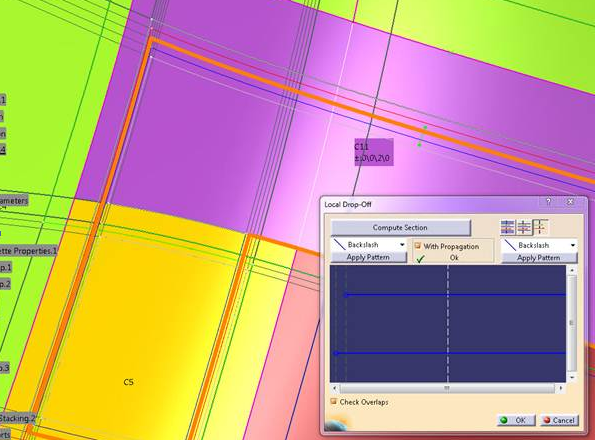
Note that the diagnostic has turned to OK. -
Select a pattern (for example Slash) and apply it.
![]()