The differences with the Flattening command are the following:
- No producibility is required before unfolding the entities.
- You can define the unfolded surface from the dialog box.
- The 2D to 3D and 3D to 2D geometry transfers are done using the
Transfer
command.
The transferred geometry is created under the ‘in work’ object (no longer in a created ‘geometry transfer’ body). - The geometry transfer is associative with origin surface and the origin geometry.
- The computation of unfolded shape does not take into account the fibers but is a pure geometrical computation.
- Open the Flattening1.CATPart document.
- Optional: Create a geometrical set named Unfold to store the Unfolded Surface.
-
Click Unfold Plies
 in the Flattening toolbar.
The Unfold Composite Entity dialog box is displayed:
-
Select the Composites entities to unfold.
- Multi-selection of entities
 is
available.
is
available. - In the multi-selection
dialog box, click
 to select entities using the
Stacking Management.
to select entities using the
Stacking Management. - Select plies, sequences, plies groups or stackings.
The entities selected must all have the same support surface.
A green tip indicates that it is the case.
Otherwise, a red cross is displayed and the buttons Apply and OK remain greyed.
We have selected the stacking.
The dialog box is updated with the number of plies and the number of cut-pieces. - Multi-selection of entities
-
Select the surface where the entities will be unfolded
or click to define one.
In the dialog box that appears, click More, and set the Surface Type to All.
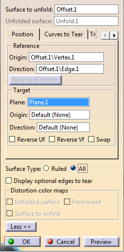
Click OK in the Unfold Definition dialog box when done.
The Unfold.1 surface is created:
If an unfolded surface has already been created for the support surface of the entities selected, the Unfolded Surface field proposes this surface. -
Click Apply.
The stacking is unfolded on the surface defined in the previous step:
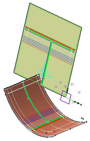
Click OK to validate and exit the dialog box.
A node Flatten Body is created under each ply with the Flatten Rosette and the Unfold Contour.
![]()