Rosette Transfer Curve uses the rosette transfer type information.
A rosette transfer curve can be used for draping simulation in producibility commands.
You can also create a rosette transfer curveinside a producibility command.
In that case, inputs are automatically proposed: Ply rosette, reference surface, orientation and the seed point.
Older models must be upgraded to the new rosette feature.
Editing a rosette transfer curve requires access to a Composites license.
-
Activate the geometrical set where you want to create the rosette transfer curve.
-
Click Rosette Transfer Curve
 in the Analysis toolbar.
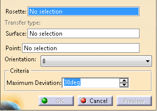
The Rosette Transfer Curve dialog box is displayed:
-
Select a rosette among those defined in the Composites Parameters.
-
Select the surface where the curve is created.
In most cases, it is the reference surface. -
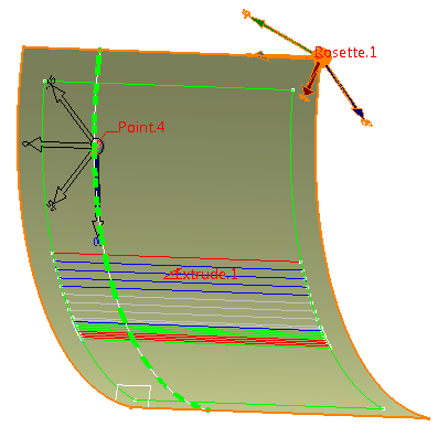
Select a passage point of the curve.
A rosette transfer preview is attached to this point. -
Choose a direction among those defined in the Composites Parameters.
-
A preview of the curve is displayed: - The Rosette is transferred at the selected point.
-
A point-direction goedesic line is created at the selected point in
the direction given by the transferred rosette at the selected
point.
Its length depends on the surface size. -
The Rosette is transferred at the end of the geodesic line.
A new geodesic line is computed from there. -
These two steps are repeated until the goedesic line is
stopped by a surface boundary, or intersetcs another
geodesic line, or itself.
This could be the case on a cylindrical surface. - The process is repeated in the other direction from the selected point.
- The Rosette cannot be transferred at the end of a geodesic line.
- The geodesic lines cannot be created.
- The deviation between the end point of a geodesic line and the transferred Rosette at this point exceeds the Maximum Deviation.
In such cases, the curve is created with the computed points, and an update warning is displayed.
A rosette transfer curve is created in the current geometric set. It can be used as any other curve on surface.
![]()