Open the ManufacturingData1.CATPart document.
-
Click Stacking Text
 in the Manufacturing toolbar.
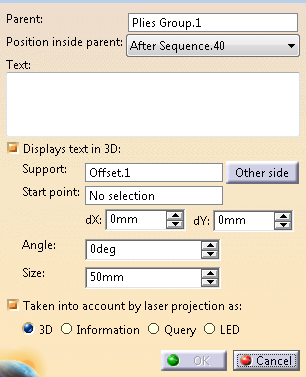
The Stacking Text dialog box opens.
-
Select the Parent of the stacking text.
It can be a stacking, a plies group, a sequence, a ply or a cut-piece.
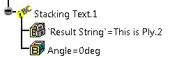
The Stacking Text node is created under the selected parent.
It can also be a flatten body. In this case:
- Position inside parent is At the end.
- Displays text is 3D is not available.
- The support surface is the plane of the flatten feature (not editable).
- The start point is the location point of the flatten
feature, if any,
the origin of the flatten plane otherwise (not editable). - Laser projection information is cleared and disabled.
- The stacking text is created under the flatten body, and
categorized as Texts.
Edit the flatten body to change the category. - Stacking text on Plies on unfold feature in not supported.
- Category may be lost during copy/cut/paste operation outside the flatten body.
-
From the list, select the position of the Stacking Text node under its parent.
The propositions in the list depend on the parent. -
Define the text.
Stacking Text supports all characters as well as the following keywords.
In the resulting text, whenever possible, a keyword is replaced by the corresponding value.
Otherwise, it remains as is in the resulting text.
The interpretation of a keyword depends on its position in the stacking as shown below:
- Stacking Plies Group Sequence Ply Cut-Piece %PARTFILENAME% Yes Yes Yes Yes Yes %PARTNUMBER% Yes Yes Yes Yes Yes %PLYGROUP% No Yes Yes Yes Yes %SEQUENCE% No No Yes Yes Yes %PLY% No No No Yes Yes %CUTPIECE% No No No No Yes %PLYORCUTPIECE% No No No Yes Yes %PLY_CUTPIECE% No No No Yes Yes/No %MATERIALNAME% Yes if only 1 material in Stacking Yes if only 1 material in Ply Group Yes if only 1 material in sequence Yes Yes %MATERIALID% Yes if only 1 material in Stacking Yes if only 1 material in Ply Group Yes if only 1 material in sequence Yes Yes %DIRECTIONNAME% Yes if only 1 direction in Stacking (unlikely) Yes if only 1 direction in Ply Group (unlikely) Yes if only 1 direction in sequence Yes Yes %DIRECTIONVALUE% Yes if only 1 direction in Stacking (unlikely) Yes if only 1 direction in Ply Group (unlikely) Yes if only 1 direction in sequence Yes Yes Optional: Clear Display text in 3D.
The text has no visual representation except for the node in the specification tree.
-
If you do not clear Display text in 3D, enter:
-
Select the Taken into account for laser projection as check box to export the stacking text.
The following text types are available:
- VIRTEK format supports all text types.
- LPT format
supports only 3D type.
In this format, all other text types are exported as <INSTRUCTIONS>. - In LASERGUIDE format, non-projected texts are exported as <COMMENT>.
- In LAP format, non-projected texts are ignored.
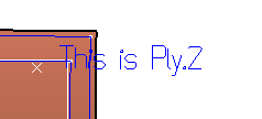
If Display text in 3D is selected, it is visible in the graphic area. This representation is not a geometry.
If the parent is a flatten body, the 3D representation depends on the category of the stacking text.
- For Texts and No Category, the stacking text has a default DXF font display.
- For all other categories, the stacking text is displayed as polylines as for laser projection.
- The text projected in the Drafting document is either an annotation or a geometry.
Copy/Cut/Paste is available.
When pasting in a plies group or a sequence, the Stacking Text is placed at the end.
You have to position it manually under the node.
You can paste a Stacking Text outside the stacking, but it will be ignored by Laser Projection Export.
If the Stacking Text is moved outside the stacking, Parent, Position inside Parent and Taken into account for laser projection as are no longer available.
![]()