This geometrical set can be created or pasted only under a ply or a cut-piece or a core.
Change Geometrical Set is not available.
Open the ManufacturingData1.CATPart document.
-
Click Additional Geometries
 in the Manufacturing toolbar.
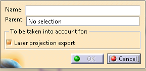
The Additional Geometries dialog box opens.
-
Optional: Enter the Name of the geometrical set.
By default, the name of the geometrical set is Additional Geometries.x. -
Select the Parent of the geometrical set.
It is either a ply, a cut-piece or a core. -
Optional: Select the Laser projection export check box under To be taken into account for.
The curves contained in the geometrical set are used in Laser Projection Export (surfaces or points are ignored).
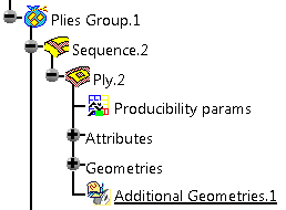
The geometrical set is created under its parent, after the Attributes and Geometries nodes.
- You add only elements supported by Laser Projection Export.
- The curves fit in the ply or the cut-piece: The curves are
discretized and elevated from the ply reference surface.
If the curves are not on the ply reference surface, the discretization points are projected on that surface before the elevation is computed.
![]()