Retrieving the Properties of a Beam Section

This task shows you how to compute beam properties from ply sections defined on your models, to analyze the structure using finite elements.

In a beam model, the finite element analysis requires information about the structural behavior of the beam, namely how it responds to loads. These properties of the beam depend on the shape and size of the beam and the material properties. In the case of a Composites structure, this can be a very complex problem, as the cross-section may contain many plies, using different materials which have non-isotropic properties.

Ply Section Beam Properties proposes an easy way to compute these properties. From the intersection of a plane with a cross-section you have defined, Ply Section Beam Properties computes the outline of the cross-section. The section is displayed in the graphic area while the Composites layup is retrieved to compute the necessary properties. You can then export the properties to a spreadsheet.

Available in Composites Engineering Design (CPE).
Open the BeamSections1.CATPart document.
Sections must already exist.
  1. Click Ply Section Beam Properties  in the Analysis toolbar.
    The Section Properties dialog box is displayed:

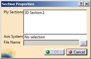
    It is populated with the sections found in the model.

  2. Select the sections to process in the list.
    Only planar sections can be processed.

  3. Select a coordinates system to define a frame of reference:
    • Its X-axis and Y-Axis are projected on the section plane.
      All sections need to be parallel to that XY plane.
    • The intersection of its Z-axis with the section plane defines the origin used to compute the properties.
    • If you do not select a coordinates system, Section Properties uses the origin and the axes of the section plane instead. In that case, it is your responsibility to define a consistent plane.

  4. Click ... to enter the path and the name of the spreadsheet to create.

  5. Click OK to validate.
    The following beam properties are exported to the spreadsheet.
    Parameter Name
    in the Spreadsheet
    Description Support in
    Analytical Solution
    Section Name Name of the cross section (string) -
    E Average Youngs modulus Yes
    AREA Cross-sectional area Yes
    EA Product of E and AREA Yes
    El11 Bending stiffness for axis 1 Yes
    El12 Cross bending stiffness Yes
    El22 Bending stiffness for axis 2 Yes
    GJ Torsional stiffness No
    MASS Mass per unit length Yes
    I11 Moment of inertia for axis 1 Yes
    I12 Moment of product of inertia Yes
    I22 Moment of inertia for axis 2 Yes
    XY1m Beam center of mass, x Yes
    XY2m Beam center of mass, y Yes
    GA11 Transverse shear stiffness, axis 1 No
    GA22 Transverse shear stiffness, axis 2 No
    GA12 Transverse shear stiffness, cross product No
    XY1c Beam centroid location, x Yes
    XY2c Beam centroid location, y Yes
    XY1s Shear center location, x No
    XY2s Shear center location, y No
    AI11 Area moment of inertia about 1-axis Yes
    AI22 Area moment of inertia about 2-axis Yes
    AI12 Area moment of inertia for cross-bending Yes
    Ox Global x position of section origin Yes
    Oy Global y position of section origin Yes
    Oz Global z position of section origin Yes
    AX1x First component of section x-axis Yes
    AX1y Second component of section x-axis Yes
    AX1z Third component of section x-axis Yes
    AX2x First component of section y-axis Yes
    AX2y Second component of section y-axis Yes
    AX2z Third component of section y-axis Yes