These sections can be created
- In one or several planes
- Along one or several curves
- As whole sections or portions
- As a realistic or a schematic
view.
You can position cores and apply a scale factor to the cores.
The
sections are created as features: They are marked as not up-to-date when the
orientation, contour, material or stacking order of the plies, or the
sectioning elements are modified. Standard update is available.
The resulting sections will be stored in the CATPart.
They can be
used in a
CATDrawing.
The case where the plies group contains plies with its draping direction and plies with another draping direction (some plies are above the surface, others are below the surface) is not supported. This case requires that you create two plies group, each with one draping direction.
Information flags are available throughout the command. They can be moved or hidden.
![]()
-
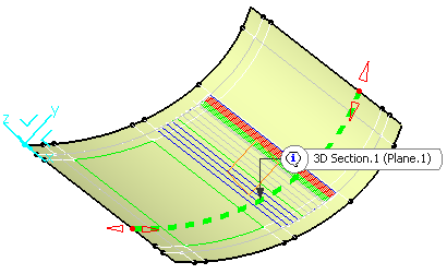
Select Sectioning planes or curves in the 3D viewer or in the specification tree.
The dialog box is updated accordingly.
A contextual menu is available to create sectioning elements.- The intersections of the sectioning
elements and the support surface
of the plies appear as dotted lines. - An information flag is attached to each sectionning element.
- Handles are attached to each end of the dotted lines.
We have selected Plane.1 in Geomerical Set.1.
- The intersections of the sectioning
elements and the support surface
-
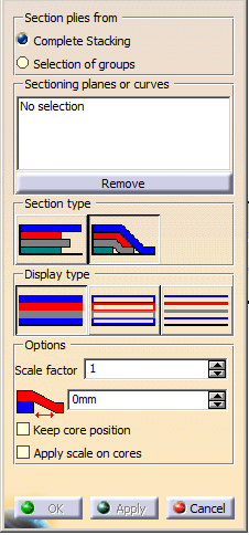
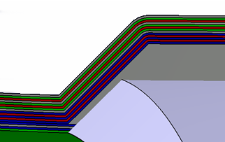
Optional: By default, the sections are computed along the whole dotted lines.
Use the handles to limit the computation to a portion of the dotted lines. -
-
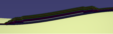
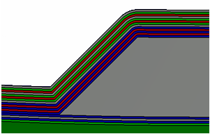
Optional: If you have selected Realistic, define a Ramp size,
i.e. the length of the small ramps added at the end of each ply as showns by the arrows below.
-
-
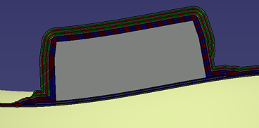
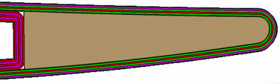
If required, key in a Scale factor, i.e. the factor by which the thickness of the element
(ply or insert) is multiplied in the section view as shown by the arrow in the picture below:
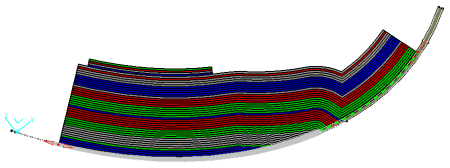
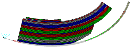
The Scale factor introduces a deformation of the section as shown below:
At the top, the Scale factor is equal to 1
at the bottom, it is higher than 1
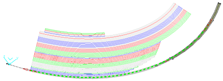
Optional: Select the Apply scale on cores check box for a better understanding
of the plies when cores exist.- The scale factor (10) is not applied to the cores
- The scale factor is applied to the cores
- The scale factor (10) is not applied to the cores
-
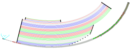
Optional: Decide if you want to keep the position of cores, or not.
By default, Keep core position is not selected.
In a case like this one
this means that the section shape of the core is repositioned
between the plies at the right position as shown below:- View of the 3D section
and core as defined in 3D:
- View of the section
only:
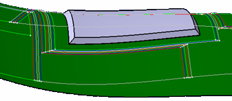
- However, in some cases,
e.g. on highly curved
reference surfaces, or core
shapes,
the repositioning of the core in the 3D section is not possible.
In such cases, when the core is designed at its correct position,
i.e. on the top surface of the plies below the core, repositioning is not required,
and selecting Keep core position provides a correct result.
- View of the 3D section
and core as defined in 3D:
-
Click Apply.
A preview of the sections is displayed. -
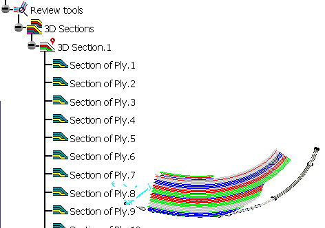
- The sections are created in the 3D viewer.
- If it did not already exist, a Review tools node is added to the specification tree.
- A 3D Sections node is created under Review tools.
- Each time you create a set of sections, it is added to the 3D Sections node, as 3D Sections.x.
- This set contains the created sections, named Section of Ply.x or Section of Cut-piece.x.
-
The sections are created as features: They are marked as not
up-to-date when the orientation, contour, material or
stacking order of the plies, or the sectioning elements are
modified. Standard update is available.
Note that:
- Inserts with concave sides are not supported:
- Cores with this shape

are deformed into
- Ramps tangent to the normal of the reference curve can lead to
instabilities:
or
- Inserts with concave sides are not supported:
Double-click a section or a set of sections to edit the sections.
Il you open a set of sections created with a previous version of the command, an information message appears.
We recommend you re-create the sections to take full advantage of the newer sections.
Ply Sections in CATDrawings
If a CATDrawing view points to a ply section and corresponds to the same
plane as the ply section,
the ply section will be visible in the CATDrawing
as illustrated below:
- L
- Surfacic or Block linear ply section:
- Light linear ply section:
![]()