The cut-pieces are created from the updatable curves built from the producibility simulation on the ply and the material roll size of the material applied to the ply.
- The plies must have the same reference surface.
- The material applied on all the plies must have the same material roll width.
- At least one producibility must exist on all the selected plies.
- The current producibility must be of Hand-Layup type and recent (upgrade may be required).
- The input point must lie on all the ply shells.
- The generated cut-pieces do not support No Splice Zones nor Butt
Splice Zones:
The result could be larger than the roll width.
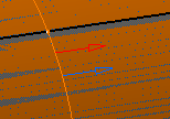
In the example below, the No Splice Zone is the red square.
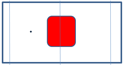
With the current input point, the cut-piece shown in orange is larger than the roll width.
By-pass: Move the input point to create curves outside those zones.
Open the Flattening1.CATPart document.
-
Click Splice Plies from Producibility
 in the Splicing toolbar.
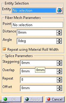
The 3D Multi-Splice dialog box is displayed.
-
Select the plies where the cut-pieces are created.
Multi-selection is available. -
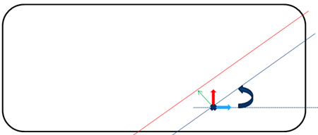
Enter the Fiber Mesh Parameters:
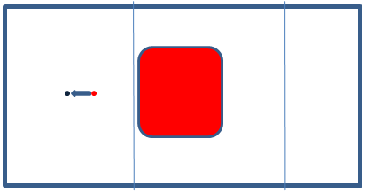
- Point: Seed point (cross). Fiber mesh curves are created on the plane tangent to the ply reference surface at the seed point.
- Distance: Offset value applied to the rotated curve to build the result curve (green arrow).
- Angle between the Warp vector and the result curve
(circular arrow).
-
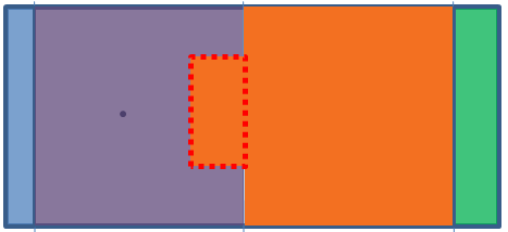
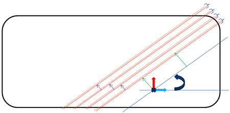
Enter the Splice Parameters to create the parallel curves (in red below):
- Staggering: Distance between the curve on a given ply and the curve on the next ply (purple arrows).
- Ovelap between to consecutive cut-pieces.
- Repeat: Defines on how many plies the staggering is applied from the start position (in the example below, 4).
- Offset: Distance by which the start position
is translated to avoid cut superposition.
-
Repeat using Material Roll Width is selected by default, to create all the cut-pieces in one shot.
The roll width is show by the dark green arrow below.
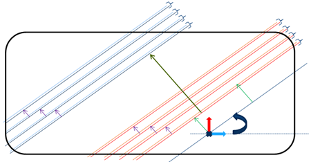
Clear it if necessary. -
Use the blue arrow to orient the ply drop, and the red arrow to orient the overlap.
The orientations are the same for all splicing curves. -
Click OK.
A 3D Multisplice Group is created.
It contains a MultiSplice From Producibility node with:- Provided parameter values (staggering, overlap, repeat status and associated offset).
- A Group of FiberMeshCurves.
The fiber mesh curves are updated after a producibility change.
![]()