Rounded Corner analyzes the sharp edges found in the contours of plies or cut-pieces and displays the corners that can be rounded.
You can then select them and quickly apply a ronded corner on them, with an editable value.
Rounded Corner does not support
- Splice zones, no drop-off zones, nor gap offsets
- Flatten contours, unfold contours
- Contours for zones
- Contours that are not associated to a composites geometry.
![]()
-
Click Rounded Corner
 in the Plies toolbar.
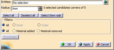
The Rounded Corner dialog box opens.
-
Select the Entities to process.
- They can be plies groups, plies or cut-pieces. Other entitites are not taken into account.
- Multi-selection
 of entities is available.
 -
 in the dialog box that opens gives access to the
Stacking Management.
in the dialog box that opens gives access to the
Stacking Management.
The selected entities are highlighted in the graphic area and listed in the dialog box, under Entities or in the multi-selection dialog box.
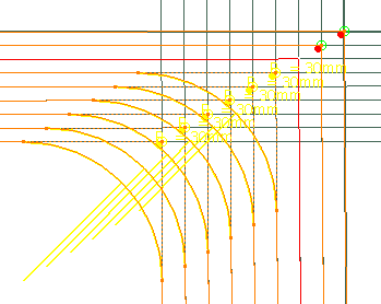
Composites Corner analyzes the entities and displays the corners that can be rounded.
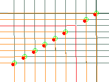
- A
candidate corner that has not yet been rounded is displayed
as a green crossed circle if it is valid,
as a black crossed circle if it is not valid. - An already rounded corner is displayed as a yellow star,
with its current radius value.
If it is not valid, the star turns black. - Corners with added material are marked with a red full circle.
The corners in the image above have not yet been rounded and have added material.
-
Draw a trap around the corners to process:
- Draw several traps with the Ctrl Key pressed to enlarge the selection.
- Draw a trap in a void area to deselect all.
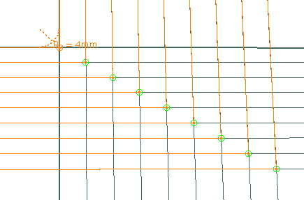
In this example, we have selected 6 corners out of the 64 candidate corners found.
The dialog box is updated with the corresponding information, for example "6 selected candidate corners out of 64". -
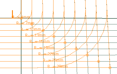
As an alternative to the selection by trap, use Select all, Deselect all or Select xmm radii, or select the corners one by one.
-
Enter a radius in the dialog box, for example 30 mm.
As the same radius is applied to the hwole selection, a message is displayed if the selection contains corner with different radii.
A preview is displayed.
-
Optional: Filter the corners to process
- Either Inner, Outer or All
- Or Material added or Material removed, or All
-
Click Apply to validate the creation of those corners.
The selection stack is now empty. -
Repeat from step 3 as required.
-
To automatically propagate a radius applied to a first corner to the following ones in its group:
- Select the first corner and apply a new radius value.
- Select other corners and click Propagate.
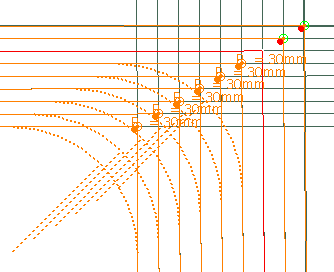
Corners are grouped according to their distance and shape.
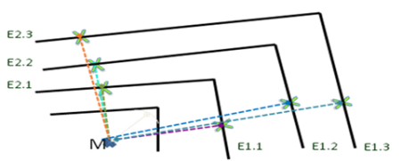
The image below shows the rounding direction in orange, and the radius propagation direction in purple.
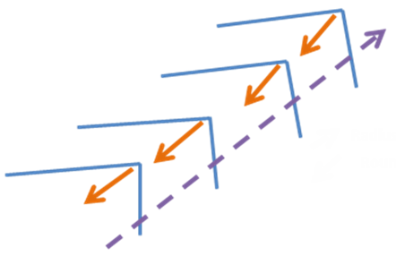
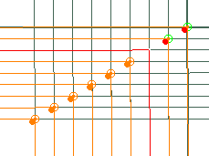
If two series of corners are close, the group is defined by the bisectors of the series, and the corners are reordered according to their abscissa along the axis defined by the average bisector of the corners.
In the image below, the group is made of corners of tow series (yellow and green).
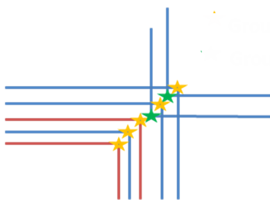
A progressive value is computed for the following corners.
The radius is computed by projecting the center of the first corner on the edges of the following corners.
- Select the first corner and apply a new radius value.
-
To regenerate a sharp corner on an existing rounded corner, set the radius to 0.
-
When you are done, click OK to validate and exit the dalog box.
-
The rounded corners are created as Rounded Corner Contour.x under the Composites Geometry of each ply.
-
Double-click a Rounded Corner Contour.x or click Composites Corner to edit rounded corners.
-
Right-click a stacking and select Stacking Object > Remove Rounded Corners to delete all the rounded corners in a stacking.
![]()