|
This task shows you how to generate the base curves of the plies
contours by slicing the solid.
The height of each ply is computed from the
solid and the thickness law information.You can generate several
Slicing Curves Group features in a CATPart, e.g. to support
collaborative design:
Several designers would slice portions of the solid
and then reconciliate the curves through the merge contour tools.
Slicing Curves Group features have their own update
mechanism that lets you track
and decide which changes of their inputs
need to be applied downstream. |
|
|
-
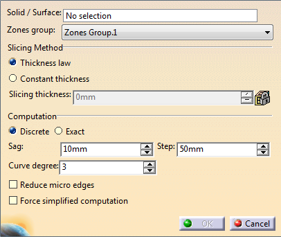
Choose the computation mode:
-
Discrete:
- The
upper
surface
of the
solid is
discretized
using a
Sag and
a Step
parameters.
- The
slicing
curves
are
computed
from
this
discretized
view,
and
smoothed
using
the
Curve
degree.
- The
default
values
of those
parameters
meet
most
required
accuracies.
However,
you can
edit
those
values.
-
Exact:
-
Offsets
of the
support
surface
of the
zone
group
are
computed,
using
either
the
thickness
law or
constant
thickness.
- The
slicing
curves
are
computed
by
projecting
the
intersections
of those
offsets
with the
solid
onto the
support
surface.
-
Sag,
Step,
and
Curve
degree
are not
required
and
become
inactive.
|
 |
Exact mode
requires that the support surface can be
offset to the maximum height. |
-
Select a
Curve degree:
The contours are
computed from the discretized view of the upper surface of the solid
and
smoothed using this curve degree.
-
Select or
clear the Reduce micro edges check box:
- By default, this check box is not selected. The slicing is
done patch by patch
(by patch, we mean the patches supporting the
surface).
- If you select this check box, the underlying patches are
grouped by tangency continuity.
This is useful with a surface with
many underlying patches as it reduces the number of edges
on the
contour and removes micro-edges.
When working with very taut parts, be careful not to select this
check box if you have set the Curve degree to 1:
the result would be
too simplified, the curves would no longer follow the design. |
-
Select or clear the Force simplified computation
check box.
- If the solid to slice is a Composites Solid From Zones, the algorithm uses properties of this solid,
making the computation
faster (Some solid top faces are offset of reference shell faces
and lateral faces are normal to the reference shell. Those
information are part of the solid from zone results).
- If the
solid to slice is a not a Composites Solid From Zones, but the
transformation of one (for example a mirror), the same
properties as explained above are retrieved, and selecting
the option makes the computation faster.
- If the solid to slice is a neither a Composites Solid From Zones
nor the transformation of one, this option has no effect: Information
cannot be retrieved, the
algorithm uses only discretization of the solid faces.
|
-
Click OK.
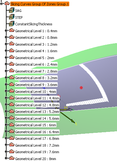
The curves are created under the node Slicing Curves Group of Zones Group.1.
They are grouped by Geometrical Level, each one corresponding to an
"altitude" of the contours.
Hide/Show is available on each Geometrical Level node.
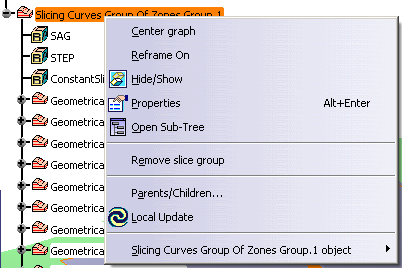
A contextual menu is available to delete a Slicing group:
|