![]()
Creating a Solid
-
Click Solid From Zones
 in the Preliminary Design toolbar.
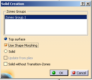
The Solid Creation dialog box is displayed.
-
Select the group of zones you want to solidify.
-
Click OK to create the solid.
The solid thickness corresponds to the addition of all thicknesses of all materials
(as defined in the Material catalog) used to design the Composites part.
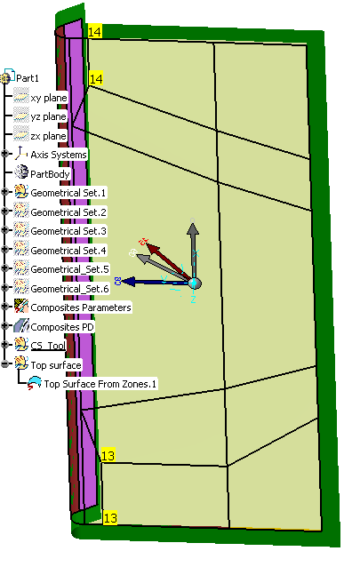
Here we created a solid from Zones Group.1.
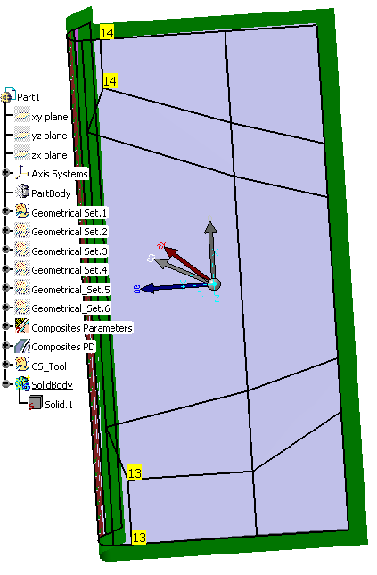
With such a solid, you can visualize the space allocation of the part.
Creating a Top Surface
-
Click Solid From Zones
to open the Solid Creation dialog box. -
Select Top Surface.
-
Click OK to create the top surface corresponding to ZonesGroup.1.
The specification tree is updated accordingly.
Creating a Top Surface with Shape Morphing
-
Open the ShapeMorphing1.CATPart document.
-
Click Solid From Zones
to open the Solid Creation dialog box. -
Select Top Surface and Use Shape Morphing.
-
Click OK to create the top surface corresponding to ZonesGroup.1 with shape morphing.
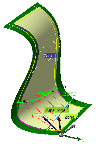
The generated top surface with shape morphing is based on the transition zone refinement curves
and takes into account the curvature of the surface.
Section view of the top surface generated with shape morphing. Section view of the top surface generated without shape morphing.
Creating a Solid with a Zero Thickness
you will need the solid to have an edge going down to the level of the reference surface
of the zone to minimize the thickness.
-
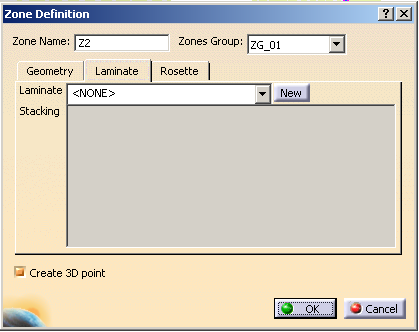
Double click Z2 (Zone 2) to make sure it has an empty laminate.
-
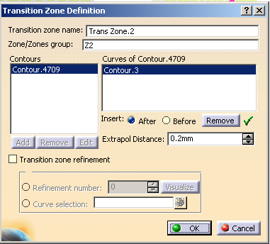
Click Transition Zone
 and select Z2 as underlying zone.
 -
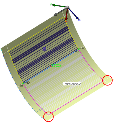
Select the contour of Z2 so that the transition zone fully covers the zone.
-
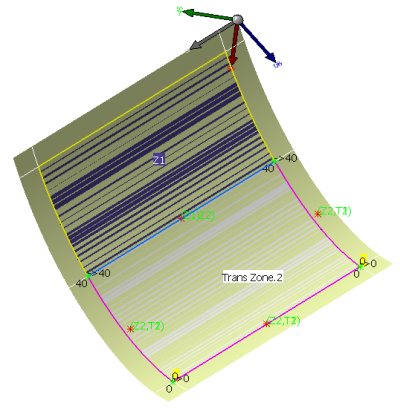
Click Connection Generator
 to display the thickness points.
 -
Select ZG_01 as the zone group to be analyzed.
-
Click Apply, then OK to close the Connection Generator dialog box.
You can see that the thickness points are not computed between Z2 and its transition zone.
-
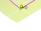
Click ITP
 .
. -
Select Point.1 as vertex, then click OK.
-
Create another ITP selecting Point.2.
-
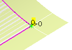
Rerun Connection Generator
on ZG_01.
This time, all the thickness points are displayed including those having a zero thickness.
-
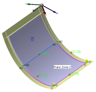
Click Solid From Zones
.
The solid is created with its edge going down to the level of the Z2 zone.
![]()